voltage problem at panel

Status
Not open for further replies.

Greg1707

Senior Member
Location
Alexandria, VA
Occupation
Business owner Electrical contractor
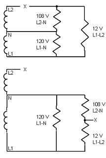
I had a service call today. The hot water heater, stove, AC etc. were not working in his house. I checked the panel and found 120 volts to neutral on each phase. When I checked the voltage phase to phase I got 12 volts. The SEC is buried and there is a meter bank in the back yard for all of the condos. I suggested he call the POCO.
What is the cause of a problem such as this?
 

Rick Christopherson

Senior Member
I would say that they have an open phase, and you are just reading the induced voltage from the live phase. That is assuming you checked the voltage with the main breaker off. If you were checking it with the main breaker on, then you were just reading the back fed voltage through the appliances.
 

drbond24

Senior Member
I would say that they have an open phase, and you are just reading the induced voltage from the live phase. That is assuming you checked the voltage with the main breaker off. If you were checking it with the main breaker on, then you were just reading the back fed voltage through the appliances.

I like this answer better. A phase to phase fault (like I said a minute ago) would read zero voltage between phases because they would be at the same potential.

Either way, you've only got one phase in the panel. The other has some kind of problem. :D
 

LarryFine

Master Electrician Electric Contractor Richmond VA
Location
Henrico County, VA
Occupation
Electrical Contractor
One line is definitely open. It can be anywhere from the transformer through the main breaker.

First test is whether any other homes on the same transformer are having the same issues.

Simple testing involves reading line-to-line voltage at each accessible point: main, meter, etc.
 

RonPecinaJr

Senior Member
Location
Rahway, NJ
I would say that they have an open phase, and you are just reading the induced voltage from the live phase. That is assuming you checked the voltage with the main breaker off. If you were checking it with the main breaker on, then you were just reading the back fed voltage through the appliances.

And people wonder why I spend hours each day reading these websites. It may seem like the simplest of service calls but nobody knows everything. Great advice, Rick!
 

philly

Senior Member
I would say that they have an open phase, and you are just reading the induced voltage from the live phase. That is assuming you checked the voltage with the main breaker off. If you were checking it with the main breaker on, then you were just reading the back fed voltage through the appliances.

Would this voltage on the open line be a result of inductance coupling, or more a result of capacitance coupling between the two wires? Would'nt 120V be a large amount of voltage to be induced?
 

steve66

Senior Member
Location
Illinois
Occupation
Engineer
Would this voltage on the open line be a result of inductance coupling, or more a result of capacitance coupling between the two wires? Would'nt 120V be a large amount of voltage to be induced?

The voltage is probably being conducted through an appliance that is connected line to line. For example, if a 240V baseboard heater is connected, it would basically be connecting the open phase to the other phase. The 12 volts drop from phase to phase probably indicates that there are also some line-neutral loads still connnected on the open phase. The L-L loads and the L-N loads connected to the open phase work as a voltage divider.

Steve
 

drbond24

Senior Member
Is it pretentious to quote oneself? :D

Sounds like a phase to phase fault to me.

I'm back to liking this explanation better. The OP said he measured 120 V from each phase to neutral. Then he measured PHASE TO PHASE and got 12 V. That means there is only 12 V difference between the two phases. He did not say that there was 120 V on one phase and 12 V on the other.

If one phase was open, there would be 0 V (or close to it) between it and neutral and 120 V (or close to it) between it and the other phase. Since both phases are at the same potential, they must be connected (phase to phase fault).

This is just my little brain trying to work through the logic of this at 9:00 in the morning. If I said something stupid I'm sure someone will call me on it. :)
 

mivey

Senior Member
Is it pretentious to quote oneself? :D


I'm back to liking this explanation better. The OP said he measured 120 V from each phase to neutral. Then he measured PHASE TO PHASE and got 12 V. That means there is only 12 V difference between the two phases. He did not say that there was 120 V on one phase and 12 V on the other.

If one phase was open, there would be 0 V (or close to it) between it and neutral and 120 V (or close to it) between it and the other phase. Since both phases are at the same potential, they must be connected (phase to phase fault).

This is just my little brain trying to work through the logic of this at 9:00 in the morning. If I said something stupid I'm sure someone will call me on it. :)
Nope. It is an open line. Read steve66's post and your 2nd post.

With line2 open, you have the original line1-neutral loads across the remaining 120 volt source, in parallel with series combination of the line2 line-neutral loads and line1-line2 loads.

If you were to cut on more line2 line-neutral loads, the 12 volts would decrease. Reduce the line2-neutral loads and the 12 volts increases. It is a voltage divider in parallel with the line1-neutral loads.
 

cadpoint

Senior Member
Location
Durham, NC
Is it pretentious to quote oneself? :D


I'm back to liking this explanation better. The OP said he measured 120 V from each phase to neutral. Then he measured PHASE TO PHASE and got 12 V. That means there is only 12 V difference between the two phases. He did not say that there was 120 V on one phase and 12 V on the other.

If one phase was open, there would be 0 V (or close to it) between it and neutral and 120 V (or close to it) between it and the other phase. Since both phases are at the same potential, they must be connected (phase to phase fault).

This is just my little brain trying to work through the logic of this at 9:00 in the morning. If I said something stupid I'm sure someone will call me on it. :)

Can I get ahead of you, in the Line to be corrected ?

I going to assume that it's a single phase 2 pole situation, so there are 180? apart. Thus if they did fault together it'd be more EMF induced voltage that there reading? No ... Yes ...

Thus the Water heater would not work required by a phase to do work never kick the bottom element on and the top and or controls will not cycle throw ...
 

mivey

Senior Member
Nope. It is an open line. Read steve66's post and your 2nd post.

With line2 open, you have the original line1-neutral loads across the remaining 120 volt source, in parallel with series combination of the line2 line-neutral loads and line1-line2 loads.

If you were to cut on more line2 line-neutral loads, the 12 volts would decrease. Reduce the line2-neutral loads and the 12 volts increases. It is a voltage divider in parallel with the line1-neutral loads.
I should have said the 12 volts will increase with more L2-neutral loads.
 

mivey

Senior Member
Like this:
OpenLinePic.jpg
 

cadpoint

Senior Member
Location
Durham, NC
Like this:
OpenLinePic.jpg

I understand what your showing, but I haven't run across a neurtal used in H20 heater yet! Not that they don't exist!

Well OK, I finally hooked up a 120v water heater, it didn't look like anything shown either, I've hooked up 240 with no neutral and doesn't look like one of those either.

The OP should Lift the circuit in question and use a meggar, or their favorite insulation tester.
 

hardworkingstiff

Senior Member
Location
Wilmington, NC
The OP stated he had 120-volts from each phase (or leg) to neutral and 12-volts between the ungrounded conductors.

If the voltage is feeding through a 240-volt load, then I would expect the voltages to be good-leg to netural around 120-volts and the bad-leg to neutral would be close 120-volts minus the voltage between legs. I believe this would hold true for a single-phase service where the ungrounded conductors were 180-degrees out of phase to the neutral. If it was (OP said condos) a 120/208-volt single-phase service then ...... I don't know.

Thoughts?
 

mivey

Senior Member
The OP stated he had 120-volts from each phase (or leg) to neutral and 12-volts between the ungrounded conductors.

If the voltage is feeding through a 240-volt load, then I would expect the voltages to be good-leg to netural around 120-volts and the bad-leg to neutral would be close 120-volts minus the voltage between legs. I believe this would hold true for a single-phase service where the ungrounded conductors were 180-degrees out of phase to the neutral. If it was (OP said condos) a 120/208-volt single-phase service then ...... I don't know.

Thoughts?
I choose to believe the voltages changed between readings. If it were 120/208 and one line was open, the result would be equivalent to what I have shown.

add: I also choose to believe "120" was a rough number, not 120.00
 
Last edited:

drbond24

Senior Member
I choose to believe the voltages changed between readings. If it were 120/208 and one line was open, the result would be equivalent to what I have shown.

add: I also choose to believe "120" was a rough number, not 120.00

I choose to believe that you're wrong and I'm right. :D

I reject your rejection of my reality and re-substitute my own.
 

Rick Christopherson

Senior Member
Would this voltage on the open line be a result of inductance coupling, or more a result of capacitance coupling between the two wires? Would'nt 120V be a large amount of voltage to be induced?
Not that it matters which mechanism is inducing the voltage, but yes, most of it would be capacitive coupling. Even though the words "Induce" and "inductive" are very similar, to induce a voltage does not exclude capacitive coupling.

The voltage is probably being conducted through an appliance that is connected line to line. For example, if a 240V baseboard heater is connected, it would basically be connecting the open phase to the other phase. The 12 volts drop from phase to phase probably indicates that there are also some line-neutral loads still connnected on the open phase. The L-L loads and the L-N loads connected to the open phase work as a voltage divider.

Steve
That is correct. If there were no line-neutral loads on the dead leg, then the voltage between the phases would be at or very near zero, because without current flowing through the 240 volt loads, the voltage drop would be zero, and both phases would have the same voltage.

With 120 volt loads present, a small amount of current will flow through the 240 volt loads onto the dead leg, and then through the 120 volt loads to the neutral. This current would be fairly low due to the resistance of the loads, but it does constitute a parallel path from the live-leg to neutral (via the dead leg).
 
Status
Not open for further replies.
Top