You are using an out of date browser. It may not display this or other websites correctly.
You should upgrade or use an alternative browser.
You should upgrade or use an alternative browser.
Is this right?
- Thread starter rattus
- Start date
- Status
- Not open for further replies.
I'm not sure. At first I thought it was the reverse switch. In general, its the current direction in the start winding that determines the direction the motor goes.
But I think it will work as described, since changing the current direction in the run winding changes the relative current direction in the Aux winding.
Steve
But I think it will work as described, since changing the current direction in the run winding changes the relative current direction in the Aux winding.
Steve
chris kennedy
Senior Member
- Location
- Miami Fla.
- Occupation
- 60 yr old tool twisting electrician
Where is the fan motor?
Where is the fan motor?
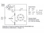
The motor is represented by two inductors--one for the run winding, and another for the auxiliary winding. They swap ends on the run winding to reverse the fan although this switch is not shown in detail.
No cigar yet:
No cigar yet:
Nope. Look closely at the switch diagram. At medium speed, you have 10uF in series with the run winding. Keep trying.
No cigar yet:
speed 2 and 3 are the same
Nope. Look closely at the switch diagram. At medium speed, you have 10uF in series with the run winding. Keep trying.
chris kennedy
Senior Member
- Location
- Miami Fla.
- Occupation
- 60 yr old tool twisting electrician
Flex
Senior Member
- Location
- poestenkill ny
What closes the uF's?
What closes the uF's?
Don't understand the question.
Flex
Senior Member
- Location
- poestenkill ny
The normally open contacts. What closes them?
M.Lee.Evans
Member
hey guys, In the medium speed position, the 4 uf is in series with the aux widing. This is in parallel with the run winding and the 4 uf cap is in series with both. I'm wondering if this is enough phase difference to start the fan? Mike
Brian Oshman
Member
- Location
- Stewartsville, NJ
It should look like this. The high circuit is wired wrong. The red conductor depicts the correct wiring.

The normally open contacts. What closes them?
This is a four position pull chain switch with the terminals marked L, 1, 2 & 3. The terminals are switched as follows:
OFF: NC
HIGH: L & 1
MED: L & 2 & 3
LOW: L & 3
quogueelectric
Senior Member
- Location
- new york
Nope. Look closely at the switch diagram. At medium speed, you have 10uF in series with the run winding. Keep trying.
Nope 2 and 3 are the same.
Give that man a box of Milky Ways and maybe a King Edward cigar!
Give that man a box of Milky Ways and maybe a King Edward cigar!
Yer right. In the HI position, full line voltage is applied to the RUN winding. In the MED and LO positions, voltage is reduced by the reactances of the 5uF caps. Voltage to the AUX winding is further reduced by the 4uF cap, and the phase shift remains constant.
This just proves you can't trust everything you see on the Net.
Give that man a box of Milky Ways and maybe a King Edward cigar!
It should look like this. The high circuit is wired wrong. The red conductor depicts the correct wiring.
Yer right. In the HI position, full line voltage is applied to the RUN winding. In the MED and LO positions, voltage is reduced by the reactances of the 5uF caps. Voltage to the AUX winding is further reduced by the 4uF cap, and the phase shift remains constant.
This just proves you can't trust everything you see on the Net.
gar
Senior Member
- Location
- Ann Arbor, Michigan
- Occupation
- EE
090612-2234 EST
The drawing and description maybe correct. We do not know how the reverse switch interacts.
In the high speed position the AUX winding is the RUN winding. Both windings may be identical or may not. I have no idea what the optimization of designing such a motor and control would be.
In low speed and medium speed the windings are as labeled. In low speed one series capacitor from the line is used providing the lowest voltage.
In medium speed two capacitors in parallel provide a higher voltage, but lower than if the two capacitors had been shorted.
Had I designed the circuit I likely would have used switch position 1 to connect to the node of the three capacitors instead of to the AUX winding.
.
Not even a candy cigarette.
Not even a candy cigarette.
Someone is ignoring the switch pattern in the diagram.
There are four scenarios:
OFF: No voltage to anything
HI: Full voltage to RUN
MED: RUN voltage dropped by current through 10UF
LO: Run voltage dropped by current through 5UF
Bear in mind now that pin 1 of the switch connects to RUN, not to AUX. That is the error.
Not even a candy cigarette.
Nope 2 and 3 are the same.
Someone is ignoring the switch pattern in the diagram.
There are four scenarios:
OFF: No voltage to anything
HI: Full voltage to RUN
MED: RUN voltage dropped by current through 10UF
LO: Run voltage dropped by current through 5UF
Bear in mind now that pin 1 of the switch connects to RUN, not to AUX. That is the error.
090612-2234 EST
Had I designed the circuit I likely would have used switch position 1 to connect to the node of the three capacitors instead of to the AUX winding.
.
That is the error as already posted. I think you would never apply full line voltage to AUX.
quogueelectric
Senior Member
- Location
- new york
Someone is ignoring the switch pattern in the diagram.
There are four scenarios:
OFF: No voltage to anything
HI: Full voltage to RUN
MED: RUN voltage dropped by current through 10UF
LO: Run voltage dropped by current through 5UF
Bear in mind now that pin 1 of the switch connects to RUN, not to AUX. That is the error.
Sorry I only followed the one line. My bad.
- Status
- Not open for further replies.