Singlephase 240V

Status
Not open for further replies.

mivey

Senior Member
Surely you guys are not going to sucker me into another discussion on this topic. You can call it anything you like, but if you are going to be technical, you must observe polarity in your measurements. The only way you can get an inverted or 180? out-of-phase waveform is to measure with polarity reversed. I am not trying to say this system cannot be utilized to effect the same result as a system with two distinct phases, 180? apart... but you cannot, within the terminological bounds of electrical power systems and distribution thereof, call the one under discussion a 2? system no matter how hard you try!!! :D
OK gar, here is where it gets tricky. See the ripples in the water around the bobber? That could mean we have a nibble. Ease back on the line ever so slightly. Not too much though, we only want to scare the little ones away...
:grin:
 

jwelectric

Senior Member
Location
North Carolina
I use Interstate 95 when trying to explain a single phase service in a dwelling unit.

I-95 runs north to south and south to north depending which side of the highway you are traveling on.

What blows people away is when I prove to them that all the cars and trucks that travel I-95 are going the same way or in other words the traffic going from north to south is going the same way as the traffic going from south to north.

Using a scope to look at the wave form of the 240 volt single phase panel we connect one channel to leg ?1? and another channel to leg ?2? and connect the ground to the grounded neutral conductor.

Let?s do the same when looking at the traffic on I-95. The grass in the middle of the two lanes of traffic is our grounded neutral so we will use this as our reference point.

While standing on the grounded neutral I face west looking at the traffic coming out of the north and heading south. I notice that this traffic is coming from my right and leaving to my left.
Now I turn around and face east and look at the traffic coming from the south heading north. This traffic is coming from my right and leaving to my left.

What I have learned by this little experiment is that no matter which way you are headed on I-95 everyone traveling on that highway is going in the same direction when I use the neutral as my reference point.
The same is true on a 240 volt single phase service.


gar

Senior Member
Location
Ann Arbor, Michigan
Occupation
EE
090904-0801 EST

Smart $:

Provide your definition for the word "phase".

If I change the phase angle between two sine waves in a two phase system, then at what phase angles does this system cease to be a two phase system, and why?

Could it be 1 deg, 0.1 deg, or what?

I think that you are trying to say that if the source of power is a single phase, then multiple phases can not be obtained from this single phase. However, there is no problem to generate any combination of phases from a single phase system.

A stock senior question by A. D. Moore was what is the maximum phase shift from an RC network (resistance capacitance). A common answer was 90 deg, and that is incorrect. The basis of the founding of the Hewlett-Packard company was an RC network that produced a 180 deg phase shift and still had a usable signal strength. This was used in the original HP audio oscillator.

Note: the phase shift of an input signal applied to the grid of a triode amplifier to the plate output is 180 deg. This tube phase shift in combination with with the RC network of 180 deg phase shift produced a 360 or 0 deg result and thus was capable of oscillation.

.
 

cripple

Senior Member
Singlephase 240V

Single phase 240/120 Residential service the transformer?s secondary, will consist of one 240 volt winding which is center taped, and referenced to earth (ground), or two winding which are connected in series and center connection is referenced to earth (ground).
In one instance from phase A to the reference point (XO) is a positive 90 degrees and from phase B to the reference point (XO) is a negative 90 degree. As we all know in alternating current phase A and B will change polarity, and will never be the same polarity in any given instance in time. The 180 degrees is in references to the XO reference point.
When I look the following in one cycle it makes it easier to understand why the neutral (grounded or referenced) conductor will only carry the unbalance load on multiwire branch circuit. With a 10 amp load on A phase (positive) and a 5 amp load on B phase (negative), the negative 5 amps will cancel 5 amps of the positive, and the neutral will be carrying the remaining 5 amps.
 

Smart $

Esteemed Member
Location
Ohio
Provide your definition for the word "phase".
I'll give you two... but I'll not claim them as mine. They are copied from Webster's Dictionaries, the first from the Collegiate Eleventh Edition, and the latter from the Revised Unabridged 1913 Edition

the point or stage in a period of uniform circular motion, harmonic motion, or the periodic changes of any magnitude varying according to a simple harmonic law to which the rotation, oscillation, or variation has advanced from its standard position or assumed instant of starting

Any one point or portion in a recurring series of changes, as in the changes of motion of one of the particles constituting a wave or vibration; one portion of a series of such changes, in distinction from a contrasted portion, as the portion on one side of a position of equilibrium, in contrast with that on the opposite side.
Note your position is more in line with the latter :cool:

If I change the phase angle between two sine waves in a two phase system, then at what phase angles does this system cease to be a two phase system, and why?

Could it be 1 deg, 0.1 deg, or what?
I'm not going to give any creedance to this... at this point in time. Read on...

I think that you are trying to say that if the source of power is a single phase, then multiple phases can not be obtained from this single phase. However, there is no problem to generate any combination of phases from a single phase system.
No. I'm not trying to say anything.

I am saying this is a single phase source. Split phase, perhaps... but nonetheless, single phase.

Answer me these questions: Is this voltage source the effect of a single or multiple magnetic fields? If single, can two equal and opposite phases exist in a single magnetic field?

A stock senior question by A. D. Moore was what is the maximum phase shift from an RC network (resistance capacitance). A common answer was 90 deg, and that is incorrect. The basis of the founding of the Hewlett-Packard company was an RC network that produced a 180 deg phase shift and still had a usable signal strength. This was used in the original HP audio oscillator.

Note: the phase shift of an input signal applied to the grid of a triode amplifier to the plate output is 180 deg. This tube phase shift in combination with with the RC network of 180 deg phase shift produced a 360 or 0 deg result and thus was capable of oscillation.

.
You are talking about circuitry and manipulation of the phenomenon of electricity using multiple circuit components... which has no bearing on this single basic electrical component. We can talk about such manipulation 'til the cows come home, and it still does not change the characteristics of the the voltage source component, i.e. the transformer.
 
Last edited:

Smart $

Esteemed Member
Location
Ohio
...
In one instance from phase A to the reference point (XO) is a positive 90 degrees and from phase B to the reference point (XO) is a negative 90 degree.
...
You'd need a third voltage at vector bearing 0? with respect to A-N and B-N to make this a valid statement.

We're having hard enough of a time in agreeing whether there is one or two vectors here as it is, let alone trying to establish a third :D
 

gar

Senior Member
Location
Ann Arbor, Michigan
Occupation
EE
090904-1649 EST

Smart $:

The signal at the input to the transformer is single phase. There are two or more output signals and thus multiple phases.

With no load on the secondary of a transformer there is a magnetic field that is out of phase with the applied voltage e = N*db/dt. When a load is place on a secondary then there is an additional magnetic field from the current in said secondary and this is counterbalanced by an added magnetic field from current in the primary. Add a second secondary and it has its associated magnetic fields from its loads. You can sum all these fields and treat them as a composite, or look at them individually.

Consider two transformers. Connect the two primaries in parallel and the two secondaries in series phased so the secondaries add. Now clearly there is no common magnetic circuit. Do you consider pair of transformers as two phases at the output or just one phase? For the purposes of this discussion this circuit provides essentially the same result as a single transformer with a center tapped secondary.

.
 

SG-1

Senior Member
my two cents

my two cents

Gar: almost thou persuadest me, but for the warning in my heart.

If I have two secondary transformer windings from different phases on a polyphase transformer I cannot parallel them.

By definition the output of a single phase transformer must be single phase.
That is why it is possible to parallel the windings by observing the polarity marks.

If the secondary were divided into 10 windings it would not be a 10 phase transformer.

Finally,
One cannot create a new phase by grounding a center tap,
just a phasor.
 

Smart $

Esteemed Member
Location
Ohio
The signal at the input to the transformer is single phase.

That statement right there will always be at the very root this entire discussion. As long as the discussion is limited to the characteristics of a basic one-primary-winding transformer, there cannot be a second phase without manipulation of the parameters affecting its output and, or the measurement thereof.


With no load on the secondary of a transformer there is a magnetic field that is out of phase with the applied voltage e = N*db/dt. When a load is place on a secondary then there is an additional magnetic field from the current in said secondary and this is counterbalanced by an added magnetic field from current in the primary. Add a second secondary and it has its associated magnetic fields from its loads. You can sum all these fields and treat them as a composite, or look at them individually.

This amounts to a "Which came first, the chicken or the egg?" discussion. While you say there is an additional magnetic field as a result of loading the secondary, another field is superimposed on the original. It is still the same field but under different conditions. The main issue here is that the single-phase primary winding creates the field, secondary only influences the field.


Consider two transformers. Connect the two primaries in parallel and the two secondaries in series phased so the secondaries add. Now clearly there is no common magnetic circuit. Do you consider pair of transformers as two phases at the output or just one phase? For the purposes of this discussion this circuit provides essentially the same result as a single transformer with a center tapped secondary.
Still single phase. ;)
 
Last edited:

gar

Senior Member
Location
Ann Arbor, Michigan
Occupation
EE
090905-0917 EST

Our differences are based on different definitions.

To continue my example of two transformers fed from the same primary single phase source. Make one of these transformers a Sola constant voltage transformer.

My experiment with 120 VA Sola model 23-22-112 with a 75 W incandescent load produced a phase shift 32 deg from from input to output. This angle was derived from voltage measurements of adding and subtracting the secondary from the primary.

Sola output was 120.7 V. The input was adjusted to 120.1 V. The Powerstat variable auto-transformer did not allow a closer input setting.

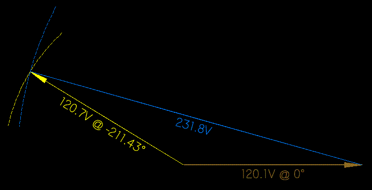
When connected for series addition of the sine waves the measured voltages were 120.1, 120.7, and 231.8 . The calculated angle from this vector diagram was 31.43 deg.

When connected for series opposition the measured voltages were 120.1, 120.7, and 66.3 . Calculated angle 32.0 deg.

Good correlation between the two measurements.

Is this a two phase system or single phase by your definition?


Next consider this arrangement. Two alternators connected together by a mechanical differential. This allows adjustment of the angle of one alternator shaft with respect to the other. When running the two outputs are synchronized sine waves. The phase angle relationship between the two outputs can be continuously adjusted from 0 to 360 deg by the mechanical position of the pinion in the differential. At what phase angles of this two phase generator is the system a two phase system vs a single phase system?

.
 

Smart $

Esteemed Member
Location
Ohio
090905-0917 EST

Our differences are based on different definitions.

To continue my example of two transformers fed from the same primary single phase source. Make one of these transformers a Sola constant voltage transformer.

My experiment with 120 VA Sola model 23-22-112 with a 75 W incandescent load produced a phase shift 32 deg from from input to output. This angle was derived from voltage measurements of adding and subtracting the secondary from the primary.

Sola output was 120.7 V. The input was adjusted to 120.1 V. The Powerstat variable auto-transformer did not allow a closer input setting.

When connected for series addition of the sine waves the measured voltages were 120.1, 120.7, and 231.8 . The calculated angle from this vector diagram was 31.43 deg.

When connected for series opposition the measured voltages were 120.1, 120.7, and 66.3 . Calculated angle 32.0 deg.

Good correlation between the two measurements.

Is this a two phase system or single phase by your definition?


Next consider this arrangement. Two alternators connected together by a mechanical differential. This allows adjustment of the angle of one alternator shaft with respect to the other. When running the two outputs are synchronized sine waves. The phase angle relationship between the two outputs can be continuously adjusted from 0 to 360 deg by the mechanical position of the pinion in the differential. At what phase angles of this two phase generator is the system a two phase system vs a single phase system?

.
I believe you are too hung up on defining a system by phase angles.

I'll add to your scenarios with another example that refutes what you are to trying to point out...

Consider a 3? delta-wye transformer. Just by the winding configuration alone, there is a 30? phase shift between input and output voltages (actual does vary, dependent on design and operation details). Now just because there is a voltage phase shift between primary and secondary voltage, do we now call this a six-phase system? No. The primary feeders are from one 3? system while the feeders leaving the secondary constitute a different 3? system.

However, I do give you credit for the imaginative scenarios you are bringing to this discussion... and they cannot be dismissed entirely. The position I'm taking in this discussion is one of convention, and I want you to know that I do completely understand the theoretical aspects which you bring to the table.

As for your generator contraption, I will concede to the notion that opposing outputs could be configured into a bona fide two phase system. I do so from the standpoint that it is generated as such, rather than starting out as pure single phase and manipulated into deviant behavior.
 

gar

Senior Member
Location
Ann Arbor, Michigan
Occupation
EE
090905-1130 EST

Smart $:

Add a wye-wye to your delta-wye and you have a six phase output from a three phase input.

Is my Sola plus a standard transformer from a single phase input a two phase output or not?

Is a so called single phase capacitor run motor a single phase motor or a two phase motor?

If I have a delay line fed with a single phase sine wave and there are multiple taps placed along the line, then do these taps constitute a multiphase system?

.
 

Smart $

Esteemed Member
Location
Ohio
090905-1130 EST

Smart $:

Add a wye-wye to your delta-wye and you have a six phase output from a three phase input.
You could also use two delta-wye's and wire one in reverse polarity and call it either split 3? or 6?, because it's not a conventional system.

Is my Sola plus a standard transformer from a single phase input a two phase output or not?
The output exhibits the qualifications of a polyphase system... but again it is an unconventional system so you can call it whatever you like.

Is a so called single phase capacitor run motor a single phase motor or a two phase motor?
Single phase... conventionally speaking. :D

If I have a delay line fed with a single phase sine wave and there are multiple taps placed along the line, then do these taps constitute a multiphase system?
Again, this is an unconventional system so you can call it whatever you like.


Geesh!!! Give a guy an inch, and he then wants a mile ;)
 

LarryFine

Master Electrician Electric Contractor Richmond VA
Location
Henrico County, VA
Occupation
Electrical Contractor
Surely you guys are not going to sucker me into another discussion on this topic.
Yes, we are, and don't call us Shirley! :grin:


Okay, you guys. For the neophytes among us, read the post to which I linked in post 5, about a pair of batteries in series. Would you call it a bi-polar power supply, or a dual-voltage supply?


For the rest of us, here's a directly-applicable analogy:

Let's say we take three transformers or a single 3-ph unit, doesn't matter which, with center-tapped-secondaries, and power the primaries the usual way with either wye or delta; it doesn't matter which.

Now, we connect all three secondaries' center taps together, leaving us with a neutral and six hot leads. (This is a great way to feed a rectified power supply, by the way.) Would you call this 3-phase or 6-phase?

For those of you who (correctly, in my opinion) see the center-tapped secondary as single-phase, you'd say it's 3-phase, but if you see it as two phases, you'd say it's 6-phase. I see it as 1-phase double-ended.


Now, when it comes to DC, such as my two-batteries-in-series example, whether it's a bi-polar supply or a dual-voltage supply does depend on the reference point, as most electronic circuits have a 'chassis' ground.

If one end of the supply, usually the DC negative, is the ground, it's a dual-voltage supply, but if the center is grounded, it is a bi-polar supply, but in both cases, there's positive at one end and negative at the other.


So, back to our center-tapped secondary, sure, from the center tap's point of view, it certainly resembles two phases, but the fact that they peak at their opposing polarities at the same time makes it a single phase.

Even if we connected two separate 1-phase transformer's secondaries in series, if the primaries are driven by a single phase, the secondaries will collectively be of a single phase. Same with them paralleled, obviously.

Just as with batteries, if the secondaries can be paralleled, they're obviously single phase. If they're in series additively, the same thing applies. If they were 180 degrees out, they'd combine subtractively.
 

SG-1

Senior Member
Sola Constant Voltage Transformer

Sola Constant Voltage Transformer

Gar, this transformer is a ferroresonant transformer. I would say you were stacking the deck if we were playing cards.

The 30 degree phase shift is caused by capacitors in the Sola.

What say ye ?
 

SG-1

Senior Member
To answer your question:

Q1. I still hold you cannot derive a polyphase system from a single phase system with transformers alone.

Q2. The angle for a two phase system was established long ago. If one planes to operate a two phase motor then 90 degrees is required. Being able to generate two phases with two single phase generators at any angle is a purely academic exercise.

I have an inquiry: How do you create a vector diagram with only voltage readings :-?
 

gar

Senior Member
Location
Ann Arbor, Michigan
Occupation
EE
090907-0635 EST

SG-1:

Your Q1. Depends upon your definition of transformer and polyphase.

Your Q2. A two phase motor can run from phase sources that are not 90 deg apart. A single phase capacitor start and run motor is one such example. Take any two phase motor and connect it to two phases of a normal 120 deg spaced three phase source and it should start and run. To make an induction or synchronous motor start and run you only need a crude rotating magnetic field. A non-rotating field can keep a motor running once it is started provided the motor is not overloaded. With an accurately designed three phase induction motor and 120 deg excitation an almost constant torque vector is created. A single phase motor running on single phase, all starting means being removed after reaching speed, produces large torque pulsations.

A bearing manufacturer used a single phase motor in a test fixture for bearing life test, and had early failure of the bearings being tested compared to the same test machine with a DC motor. This was because of the velocity modulation of the shaft from the torque pulsations.

Your Q3. Three vectors related to one another create a triangle. 120.1 and 120.7 are legs of a triangle, and 231.8 is the hypotenuse of a right triangle formed by 120.1 + X, and Y. Then X and Y are the sides of another right triangle with hypotenuse 120.7 . From this the angle between the 120.1 and 120.7 vectors can be calculated.

.
 

Smart $

Esteemed Member
Location
Ohio
I have an inquiry: How do you create a vector diagram with only voltage readings :-?
Your Q3. Three vectors related to one another create a triangle. 120.1 and 120.7 are legs of a triangle, and 231.8 is the hypotenuse of a right triangle formed by 120.1 + X, and Y. Then X and Y are the sides of another right triangle with hypotenuse 120.7 . From this the angle between the 120.1 and 120.7 vectors can be calculated.

Illustration...

vectorsbytriangle.gif


Note the vector angle may be on the other side of –180? at –148.57?.
 

mivey

Senior Member
By definition the output of a single phase transformer must be single phase.
who's definition?
If the secondary were divided into 10 windings it would not be a 10 phase transformer.
I don't think anyone is making that claim
One cannot create a new phase by grounding a center tap
You create a two-phase system, but that is as far as you can go using that method.
I believe you are too hung up on defining a system by phase angles.
I believe you are too concerned with the source. As far as a n-phase system goes, the system is defined by its characteristics, not what was used to create it. It is the phase angles that define the system in the classic definition. An n-phase system has a 360/n degree displacement between the voltages.

...Let's say we take three transformers or a single 3-ph unit, doesn't matter which, with center-tapped-secondaries, and power the primaries...
If we have n-voltages with 360/n degree displacements, we will have an n-phase system and it would not matter how you created it.
To answer your question:

Q1. I still hold you cannot derive a polyphase system from a single phase system with transformers alone.
And you would be wrong, but a 2-phase system would be the limit using the center-tap method.
Q2. The angle for a two phase system was established long ago. If one planes to operate a two phase motor then 90 degrees is required. Being able to generate two phases with two single phase generators at any angle is a purely academic exercise.
The historically-labeled 2-phase system is an anomaly that does not follow the standard n-phase system naming convention. It could be more accurately described as part of a 4-phase system.
 

Smart $

Esteemed Member
Location
Ohio
...
I believe you are too concerned with the source. As far as a n-phase system goes, the system is defined by its characteristics, not what was used to create it. It is the phase angles that define the system in the classic definition. An n-phase system has a 360/n degree displacement between the voltages.
As you noted later in your post, the archaic but conventional two-phase system is an anomaly. In fact, any multiphase system with unequal-rotational-waveform displacement would be an anomaly to your recognized defintion. So you are citing but one definition of polyphase system voltages.

Wordnet defines polyphase as "of an electrical system that uses or generates two or more alternating voltages of the same frequency but differing in phase angle"

The point of contention is split phase systems can be defined and measured as two voltages with the same phase angle. This is an anomaly by your recognized definition and others which disqualifies it as a member.
 
Status
Not open for further replies.
Top