Equipment grounding conductor sizing for increased phase conductors

Status
Not open for further replies.

Smart $

Esteemed Member
Location
Ohio
ok lets do it this way.

I did the calculations of the OP in this thread, with the given information

400' of 300Kcmil
400' of #6 EGC

going from the resistance table 8 in chapter 9 at 75?C resistance

300 Kcmil has a resistance of .01784 @400 feet
# 6 has a resistance of .204 @400 feet
this gives us a total fault circuit resistance of .22184

If the voltage from the ungrounded to the X0 is 120 volts you will have about 541 amps of fault current.

if the voltage from the ungrounded conductor to the X0 is 277 volts you will have about 1248.6 amps of fault current

if at 240 volts expect around 1081.8 amps


now every one of these will open a 150 amp breaker.

so why would we need a larger EGC other than the code says so.

The only time would be, if the panel with the breaker in it is also fed by a very long run and has feeders conductors close to the size of the circuit breaker feeding this circuit, like when we see a 200 amp panel feeding a 150 amp circuit, it might be a problem if the 200 amp has long feeders? this is why we need to have a PE stamp to say the #6 is ok

I just don't see it, and as Bob said in post 8 this code change was not made in the realm of safety. It was for the convenience of inspectors.

If I'm wrong in my caculations for a fault let me know:)
Now look at your exercise from the viewpoint of running 3/0 for the same circuit, but at a distance having the same resistance. That figures out to 232ft. Yet you are required to run a #6 for this circuit, too. Why do you not complain that a smaller grounding conductor is ok for this circuit?

As mentioned by Bob Alexander, IIRC, not all fault are full bolted faults. Your exercise, is only covering that possibility. Did you consider the possibility and the affect on the operation of the breaker if the fault was not a full bolted fault? Would not a larger grounding conductor increase the liklihood a breaker will open on a less than full bolted fault?

Additionally, this issue is also about affording protection to the conductors. At the instance a full bolted fault occurs, the temperature of the conductor rises. Upon exceeding the amperage at which the conductor is 75?C (the temperature at which you determined fault current), the resistance increases even more, so your calculated currents are not valid. I surmise the actual value is less than you calculated, but without researching the matter, I don't know the formula that will accurately calculate the amperage.

One issue that I do know which makes a difference is the fact that damage to 75?C thermoplastic-insulated conductors is considered to not occur until the conductor, during a fault, reaches a temperature of 150?C. Given that temperature is roughly, directly proportional to the ΔI? ratio, the current at which damage occurs is less than double the ampacity of the conductor. So the ocpd must open in time to keep the RMS fault current from reaching that value.
 

SG-1

Senior Member
If the voltage from the ungrounded to the X0 is 120 volts you will have about 541 amps of fault current.

if the voltage from the ungrounded conductor to the X0 is 277 volts you will have about 1248.6 amps of fault current

if at 240 volts expect around 1081.8 amps


now every one of these will open a 150 amp breaker.

so why would we need a larger EGC other than the code says so.

The only time would be, if the panel with the breaker in it is also fed by a very long run and has feeders conductors close to the size of the circuit breaker feeding this circuit, like when we see a 200 amp panel feeding a 150 amp circuit, it might be a problem if the 200 amp has long feeders? this is why we need to have a PE stamp to say the #6 is ok


If I'm wrong in my caculations for a fault let me know:)
I think the only thing that has not been discussed is how much longer will it take for the OCPD to operate if the EGC is not upsized with the ungrounded conductors. The longer it takes to trip the hotter the EGC. Could it reach a temperature to damage the insulation on the ungrounded conductors before the OCPD operates if the EGC is not upsized ? A few more cycles would mean a lot more heat.
 

hurk27

Senior Member
I think the only thing that has not been discussed is how much longer will it take for the OCPD to operate if the EGC is not upsized with the ungrounded conductors. The longer it takes to trip the hotter the EGC. Could it reach a temperature to damage the insulation on the ungrounded conductors before the OCPD operates if the EGC is not upsized ? A few more cycles would mean a lot more heat.

If the OCPD didn't open I would think that the EGC would heat up much faster that the 300Kcmil, even act like a fuse?

And smart is right about that part, but as I don't have the time curves for breakers here, I would think 541 amps on a 150 amp breaker would open it very fast.

as for the part of "not all fault are bolted faults, yes this is true, but so is any regular circuit that has not even been or needed to be up sized for voltage drop, as I said in my first post, the only way to protect from a high resistance fault is AFCI or GFCI, but that is a "what if"

but I still think a PE should be able to put a stamp on a smaller EGC, as in the OP question, but as the code is now he can't

Maybe a chart that gives a more closer sizing, we could size the EGC from when up sizing conductors for voltage drop?

Also think about article 430 allowing us to use smaller conductors when a motor has OVL's you can wind up with #14's on a 50 amp breaker? as they are there for fault protection, and the same issue applies.
 
Last edited:

charlie b

Moderator
Staff member
Location
Lockport, IL
Occupation
Retired Electrical Engineer
I will offer my support to three of Bob's observations, since you didn't care for being told you were wrong, without supporting information.
Just because the conductor is upsized does not necessarily increase the fault current at the end of the circuit.
Yes it does. It must. Take two resistors in series, and put a voltage across them, and you will get some value of current. Reduce the resistance of one of them, without changing the other, and the current will get higher. Upsize the ungrounded conductor, without upsizing the EGC, and the fault current will be higher than it would have been before upsizing the ungrounded conductor. Simple Ohm's Law application.

. . . I've yet to see any method which accounts for "already warm" conductors.
No need. The impact of the temperature rise in a conductor from normal operation is insignificant. Yes, resistance increases with temperature. But in the formula, temperature is expressed in units of degrees kelvin. So if the temperature in a conductor rises from 30C to 40C, for example, that is not a 33% rise. Instead, it is treated as a rise from 303K to 313K, a 3% rise.

Perhaps different calculations, but the fault current calculation should take into account the voltage drop . . . of the circuit.
Not at all. The fault current depends only on the voltage at the source and the resistance of the fault path. Here again, it is a simply Ohm's law calculation. True, if the resistance of a conductor is higher, then the voltage drop along that conductor is greater. So resistance has an impact on both the voltage drop calculation and the fault calculation. But we don't need to determine the voltage at the fault point, or to determine the voltage drop along a conductor during a fault situation. All we need to know is the amount of fault current. That value tells us how the OCPD will react, and tells us what rating we need for the affected equipment.


rbalex

Moderator
Staff member
Location
Mission Viejo, CA
Occupation
Professional Electrical Engineer
First I thank Wayne for taking the time to actually do the calcs.

Since my name was invoked with regard to the likelihood of the fault not being bolted, I?ll add this: careful analysis of the various arc-flash calculation methods in NFPA 70E, Annex D indicate that energy releases each method is valid for is essentially an I^2t (I squared t) phenomenon for short periods of time. That is, for short periods of time, typically 2 seconds or less, energy released and damage done is proportional to the square of the current times duration. As time increases beyond that, various heat dissipation phenomena begin to influence the results.

Of particular interest to our current discussion, LV OCPs that respond to both short circuits and ground faults and sometimes take a while to operate, is Section D.7.7. (the IEEE 1584 method) which states:

The range of available three-phase bolted-fault currents, Ibf, is from 700 A to 106,000 A. Each equation is applicable for the range

I1 <Ibf < I2

where:

I2 = the interrupting rating of the CB at the voltage of interest.
I1 = the minimum available three-phase, bolted, short-circuit current at which this method can be applied. I1 is the lowest available three-phase, bolted, short-circuit current level that causes enough arcing current for instantaneous tripping to occur or for circuit breakers with no instantaneous trip, that causes short-time tripping to occur.
It then mentions how to determine I1 and Ibf. Following that is a Table of application equations for various Voltage and Ampere ranges for various LV circuit breaker types.

The Section on fuses is similar in analysis and application, but Section D.7.7 is easier to follow.

The key here is to understand, for practical purposes, once a circuit has been determined to be within the application range of the analytical method, if the breaker will trip at all, both the current magnitude and the time it takes to trip are irrelevant for arc-flash purposes.

While I cannot guarantee a bolted fault, I can establish the maximum impedance for the combined line and EGC circuit for which tripping will occur. Any EGC that does not cause that maximum impedance to be exceeded is valid.

What about cases where dangers other than arc-flash are caused by a prolonged ground fault? Indeed, what about it? Those are cases where other forms of ground fault detection, such as GFCI, are necessary. But again, in those alternate detection schemes, the EGC size is not a determining factor of their effectiveness.

The issue with 250.122 "up sizing" is that it is a general solution in search of a real problem ? and it can?t find one. It is either irrelevant or inadequate. The only thing it does is make visual inspections simpler ? but not safer.
 

rbalex

Moderator
Staff member
Location
Mission Viejo, CA
Occupation
Professional Electrical Engineer
No - just unnecessarily more expensive.

In all honesty, I bought into the voltage drop argument myself for a long time, especially in the cases where the OCPD was to clear both short circuits and ground faults based on overcurrent alone. In my own refinery design background, cable tray systems became popular but branch circuits, often well over 1000?, were also common, so voltage drop in general and motor starting voltage drop in particular virtually always led to upsizing.

Now upsizing only for motor starting shouldn?t require altering the EGC because it doesn?t ultimately alter the ground fault detection/clearing effectiveness of the OCPD. Since TC cables usually came with ?one-size-larger? EGCs and upsizing cables still brought larger EGCs automatically, upsizing for motor starting only was rarely a problem and truthfully I ignored it anyway.

But 2002 came around and it became a nightmare, especially with paralleled cables, where you had no prayer of getting a suitable standard construction. I did a few of ?Wayne?s calcs? and convinced myself that the ?ground fault detection? was still intact but the effectiveness part might be compromised because the clearing time was increased.

At the same time I was on the 70E TC. I wasn?t part of the arc-flash working group, but I was aware of their findings. That was my epiphany ? upsizing an otherwise properly sized and effective EGC made no difference, especially since most of my designs had other ground fault detection means.
 

Smart $

Esteemed Member
Location
Ohio
Smart $ said:
Just because the conductor is upsized does not necessarily increase the fault current at the end of the circuit.
Yes it does. It must. Take two resistors in series, and put a voltage across them, and you will get some value of current. Reduce the resistance of one of them, without changing the other, and the current will get higher. Upsize the ungrounded conductor, without upsizing the EGC, and the fault current will be higher than it would have been before upsizing the ungrounded conductor. Simple Ohm's Law application.
Yes it is a simple application of ohm's law... but you like bob and wayne are comparing equal length circuits of two different size conductors. Due to voltage drop, we are not using the regular size conductor. So regarding available fault current, the proper comparison is the regular size conductor at a length where its resistance/impedence is equal to that of the upsized conductor at the full desired circuit length. As I pointed out above, that would be, using the method employed by wayne, 300kcmil@400' vs. 3/0@232'. These sizes coupled with their circuit lengths have the same amount of voltage drop. In both cases, the available fault current (ccc to ccc) at the load end is equal. Now if we use the requiured size grounding conductor of #6 for the 3/0@232' circuit, what size grounding conductor is necessary to afford the same resistance/impedence at 400'?

I am not saying this is an exacting way to determine the proper size grounding conductor, but I do believe it is perhaps close to the rationale behind 250.122(B). Additionally, it has been mentioned this is to make it easy for inspectors... but at the same time it makes it easy for electricians to size the grounding conductor without employing an engineer to calculate it for them (if it were once again permitted), or both inspectors and electricians learning how to calculate it themselves in addition to being permitted to do so.


Smart $ said:
. . . I've yet to see any method which accounts for "already warm" conductors.

No need. The impact of the temperature rise in a conductor from normal operation is insignificant. Yes, resistance increases with temperature. But in the formula, temperature is expressed in units of degrees kelvin. So if the temperature in a conductor rises from 30C to 40C, for example, that is not a 33% rise. Instead, it is treated as a rise from 303K to 313K, a 3% rise.
Yes the impact of temperature rise is insignificant for a bolted fault upon which the ocpd effectively opens substantially before a half cycle occurs... but what about a resistive fault which takes longer for the ocpd to "recognize" and open. While the fault is occurring, and before the ocpd opens, the conductor temperature is rising and thus affecting the resistance of the circuit... which I believe can be significant. We must remember that the grounding conductor in many to most cases is smaller than the circuit conductors, where temperature rise has a greater impact on resistance during the fault. Being the grounding conductor is in close proximity to the circuit conductors, it is most likely already at a temperature above ambient, perhaps even close to that of circuit conductors, if the fault occurs while the circuit is conducting at maximum load.

If we are to discuss this aspect of a ground fault, let's use an example of a purely resistive load where the ground fault occurs exactly at the load's midpoint, effectively doubling the current. Additionally, let's say all the conductors including the grounding conductor are 75?C-rated and operating at 75?C under a normal non-continuous load at the instant the fault occurred.

Smart $ said:
Perhaps different calculations, but the fault current calculation should take into account the voltage drop . . . of the circuit.

Not at all. The fault current depends only on the voltage at the source and the resistance of the fault path. Here again, it is a simply Ohm's law calculation. True, if the resistance of a conductor is higher, then the voltage drop along that conductor is greater. So resistance has an impact on both the voltage drop calculation and the fault calculation. But we don't need to determine the voltage at the fault point, or to determine the voltage drop along a conductor during a fault situation. All we need to know is the amount of fault current. That value tells us how the OCPD will react, and tells us what rating we need for the affected equipment.
*** Yes it is the current level we are after... but voltage drop directly corrrelates with current drop for the resistive component of the circuit. At least it did the last time I checked. For C and L components, additional considerations must be made, for they can act as a second voltage source during a fault. Aside from that, my first comment in this post covers the issue of how current is affected by the resistance/impedence of the circuit.

*** ...and conductors.
 

Smart $

Esteemed Member
Location
Ohio
No - just unnecessarily more expensive.

In all honesty, I bought into the voltage drop argument myself for a long time, especially in the cases where the OCPD was to clear both short circuits and ground faults based on overcurrent alone. In my own refinery design background, cable tray systems became popular but branch circuits, often well over 1000’, were also common, so voltage drop in general and motor starting voltage drop in particular virtually always led to upsizing.

Now upsizing only for motor starting shouldn’t require altering the EGC because it doesn’t ultimately alter the ground fault detection/clearing effectiveness of the OCPD. Since TC cables usually came with “one-size-larger” EGCs and upsizing cables still brought larger EGCs automatically, upsizing for motor starting only was rarely a problem and truthfully I ignored it anyway.

But 2002 came around and it became a nightmare, especially with paralleled cables, where you had no prayer of getting a suitable standard construction. I did a few of “Wayne’s calcs” and convinced myself that the “ground fault detection” was still intact but the effectiveness part might be compromised because the clearing time was increased.

At the same time I was on the 70E TC. I wasn’t part of the arc-flash working group, but I was aware of their findings. That was my epiphany – upsizing an otherwise properly sized and effective EGC made no difference, especially since most of my designs had other ground fault detection means.
I too have refinery experience, but likely nowhere close to yours. Also have experience in several heavy industrial installations, such as power plants. I bring this up only to point out that, ground fault detection schemes aside and in most situations of this type, the equipment grounding conductor is only but one path of multiple, if not a multitude of ground fault clearing paths. The grounding conductor run with the circuit conductors seldom realizes the full fault current of a ground fault. This is also true in many other installations. The code makes no allowance for these installations. Yet we do have to consider the circuits where the grounding conductor is the only ground fault current path!!!
 
Last edited:

rbalex

Moderator
Staff member
Location
Mission Viejo, CA
Occupation
Professional Electrical Engineer
You are correct on at least two points with regard to the ground fault current: it will probably take multiple paths and it probably won't be a maximum. However, if you have understood my previous arguments, you would recognize it doesn't matter. For an OCPD that reponds to overcurrent only, the effective arc-flash is essentially unaffected by time. If it doesn't trip, upsizing the EGC won't correct the problem and some other regognized form of ground-fault detection is necessary - which, BTW will work regardless of multiple paths or the ground fault's magnitude.

You are also correct that the NEC
 

Smart $

Esteemed Member
Location
Ohio
You are correct on at least two points with regard to the ground fault current: it will probably take multiple paths and it probably won't be a maximum. However, if you have understood my previous arguments, you would recognize it doesn't matter. For an OCPD that reponds to overcurrent only, the effective arc-flash is essentially unaffected by time. If it doesn't trip, upsizing the EGC won't correct the problem and some other regognized form of ground-fault detection is necessary - which, BTW will work regardless of multiple paths or the ground fault's magnitude.

You are also correct that the NEC
Yes, I understand your arguments. Yet I see your arguments as mostly concerning arc flash mitigation, and thus a recommendation of using ground fault detection as the best prevention for this particular safety concern. However, not all ground faults result in arc flash. Short of having ground fault detection (or the possibility of defective detection) is all the more reason to optimize the effectiveness of an overcurrent protective device for life and health safety first, equipment and wiring methods thereafter.

...and no, I do not represent the any wire manufacturer ;)
 

hurk27

Senior Member
Yes, I understand your arguments. Yet I see your arguments as mostly concerning arc flash mitigation, and thus a recommendation of using ground fault detection as the best prevention for this particular safety concern. However, not all ground faults result in arc flash. Short of having ground fault detection (or the possibility of defective detection) is all the more reason to optimize the effectiveness of an overcurrent protective device for life and health safety first, equipment and wiring methods thereafter.

...and no, I do not represent the any wire manufacturer ;)

I think Bob is referring to arc flash to show that increasing the EGC or available fault current will have no effect in a high resistance fault, if at lets say the 541 amps I have posted for 120 volt, and the ungrounded conductor in a piece of equipment were to short to the frame, and the EGC in the cable feeding the equipment was loosely connected to the junction box, putting that same 541 amps across this bad connection would most likely blow it apart, hence arc flash, or it welds to a bolted fault and trips breaker. now shorten the EGC or make it bigger, do you think the results will be any different with a higher available fault current across the same connection? current will open the weakest link. Higher current will just open it faster.:D
Even on a normally sized circuit.
 

hurk27

Senior Member
I guess I need to add :

Is there a point in length of a circuit that eventually the EGC would need to be up sized? well sure, run the above circuit 800' you would only have 270.5 amps, 1600' would not even open a 150 amp breaker.

but someone needs to be able to do the calculations, and someone must accept it.
 

Smart $

Esteemed Member
Location
Ohio
I guess I need to add :

Is there a point in length of a circuit that eventually the EGC would need to be up sized? well sure, run the above circuit 800' you would only have 270.5 amps, 1600' would not even open a 150 amp breaker.

but someone needs to be able to do the calculations, and someone must accept it.
I do not disagree with the aspect of a fault you are bringing to the table. But you are getting closer to the premise of my argument. You agree at some length the grounding conductor should be upsized. Where we haven't reached an agreement is that the upsizing should be optimized for any type of ground fault. You are still focused on bolted faults. A partial, or otherwise resistive, non-arcing ground fault could occur at a shorter distance which shall we say mimics a bolted fault at a longer distance.

Smart $ said:
If we are to discuss this aspect of a ground fault, let's use an example of a purely resistive load where the ground fault occurs exactly at the load's midpoint, effectively doubling the current. Additionally, let's say all the conductors including the grounding conductor are 75?C-rated and operating at 75?C under a normal non-continuous load at the instant the fault occurred.

Should we ignore the possibility of this type of fault?
 

Smart $

Esteemed Member
Location
Ohio
If we are to discuss this aspect of a ground fault, let's use an example of a purely resistive load where the ground fault occurs exactly at the load's midpoint, effectively doubling the current. Additionally, let's say all the conductors including the grounding conductor are 75?C-rated and operating at 75?C under a normal non-continuous load at the instant the fault occurred.
Should we ignore the possibility of this type of fault?
I did some calculation on the withstand time for the above scenario...
Code:
AWG		Ampacity	cmil area	SCC	Withstand for 75?C
#6		65A		26240		300A	21sec
#4		85A		41740		300A	54sec
#3		100A		52620		300A	86sec
#2		115A		66360		300A	137sec
#1		130A		83690		300A	218sec
				
3/0		200A		167800		300A	877sec
4/0		230A		211600		300A	1394sec
250kcmil	255A		250000		300A	1946sec
300kcmil	285A		300000		300A	2803sec

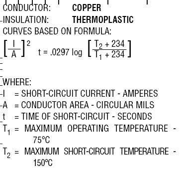
...using this formula...

withstandformula.gif

This trip curve for a 150A Sq D breaker indicates the trip time at 300A (2? rated current) could range from 12 to 400 seconds if I am reading the curve properly (1st attempt at such).


As you can see from the calculated withstand times, there is a good likelihood of the grounding conductor's insulation being damaged... and for some reason I doubt the time calculation takes into account an "already warm" conductor. It's not so much that we should be overly concerned with this alone, but we must consider the grounding conductor being in close proximity to the circuit conductor and its damaging temperature and effects migrating outward and thereby accelerating damage to the circuit conductor... perhaps even creating another fault.
 

don_resqcapt19

Moderator
Staff member
Location
Illinois
Occupation
retired electrician
I did some calculation on the withstand time for the above scenario...
Code:
AWG        Ampacity    cmil area    SCC    Withstand for 75?C
#6        65A        26240        300A    21sec
#4        85A        41740        300A    54sec
#3        100A        52620        300A    86sec
#2        115A        66360        300A    137sec
#1        130A        83690        300A    218sec
                
3/0        200A        167800        300A    877sec
4/0        230A        211600        300A    1394sec
250kcmil    255A        250000        300A    1946sec
300kcmil    285A        300000        300A    2803sec
...using this formula...
withstandformula.gif
This trip curve for a 150A Sq D breaker indicates the trip time at 300A (2? rated current) could range from 12 to 400 seconds if I am reading the curve properly (1st attempt at such).


As you can see from the calculated withstand times, there is a good likelihood of the grounding conductor's insulation being damaged... and for some reason I doubt the time calculation takes into account an "already warm" conductor. It's not so much that we should be overly concerned with this alone, but we must consider the grounding conductor being in close proximity to the circuit conductor and its damaging temperature and effects migrating outward and thereby accelerating damage to the circuit conductor... perhaps even creating another fault.
Nice work. For those that don't want to do all of the calculations you can use the I^2t numbers from the 150C column in this document divided by the current squared.
However I am not sure how valid the table is for times that exceed 5 seconds. For example if you use the 5 second ampere squared seconds value of 47346 for a #14 and use a current of 15 amps, you find that the temperature will reach 150C in 210 seconds and that does not happen.
 

hurk27

Senior Member
Ok after crunching in all this information (I think my brain got tired:confused:)

I came to the conculsion the the 120 volts to ground circuit might be a problem?

the 541 bolted fault amps would be a multiplyer of 3.6 for the Square D QOD breaker chart, this would give the 150 amp breaker a clearing time of 1.125 seconds to 30 seconds. The 5 second ICEA 150?C rating for #6 is 621.27 amps which means the insulation will be damaged in about 6 to 7 seconds at 541 amps, since it falls between the 1.125 to 30 seconds it looks like it can be damaged if I'm reading the QOD chart correctly, I can't belive it has that big of a window, but it seems to? I dont remember insta-trip breakers having this?

but a #4 looks like it would do just fine

If the voltage to X0 was 277 volts, the #6 would not be a problem, even at 240 volts.

Guys I'm learning too so go easy on me:D
 

hurk27

Senior Member
I do not disagree with the aspect of a fault you are bringing to the table. But you are getting closer to the premise of my argument. You agree at some length the grounding conductor should be upsized. Where we haven't reached an agreement is that the upsizing should be optimized for any type of ground fault. You are still focused on bolted faults. A partial, or otherwise resistive, non-arcing ground fault could occur at a shorter distance which shall we say mimics a bolted fault at a longer distance.


Should we ignore the possibility of this type of fault?

The problem with a resistive fault is just that, resistance is current limiting and pumping in more current just makes things get hotter more quickly, I cant see any difference if a resistive fault were to occur half way up the circuit or at the end, other then at half way up the circuit it will have a higher available current across it, which would cause a higher level of heating?

If I put a resistor across a voltage that exceeds it handling capability it will burn up, if I increase the current across this same resistor what's going to happen? I would think it will burn up faster?;)

The only way I know to protect from this is ground fault detection, such as AFCI, GFCI, or GFP.
 
Last edited:

Smart $

Esteemed Member
Location
Ohio
The problem with a resistive fault is just that, resistance is current limiting and pumping in more current just makes things get hotter more quickly, I cant see any difference if a resistive fault were to occur half way up the circuit or at the end, other then at half way up the circuit it will have a higher available current across it, which would cause a higher level of heating?

If I put a resistor across a voltage that exceeds it handling capability it will burn up, if I increase the current across this same resistor what's going to happen? I would think it will burn up faster?;)

The only way I know to protect from this is ground fault detection, such as AFCI, GFCI, or GFP.
Sure ground fault detection affords better protection, but it is not required in many situations.

Backing up to the first part of your post, it appears you have some grasp on the heating affect, but it seems that you have yet to associate the lower current fault with the time it takes for the breaker to open the circuit, and that the conductors insulation is more likely to be damaged as a result than that of a full bolted fault.

Through all this discussion, I've brought up several scenarios in which the variables are not accounted for in the grounding conductor sizing scheme for overcurrent fault clearing methods that I've read to date. It seems as they all deal only with full bolted faults. They do not account for the variables of circuit length, temperature of conductors at the onset of a fault event, nor the conductor withstand times for resistive faults.

At this point I feel I've exhausted my drive to make a point and do not care to reiterate the issues presented. The better part of that sentiment is a result of knowing how hard it is to buck conventional wisdom... ;)
 
Status
Not open for further replies.
Top