How does current flow in a circuit?

Status
Not open for further replies.

Smart $

Esteemed Member
Location
Ohio
You still have a current sense. You are using the voltage polarity & power factor to derive the current sense. :roll:
Current sense as you are using it is embedded in the physics of the event. Ohms Law still applies. What if the load were removed from the circuit? Wouldn't the voltage still be present and measurable. Current is zero, right? What if you removed the node (i.e. opened all pathways at the node)? Wouldn't the voltage still be present across the conductor ends? Again, current is zero, right?

My point remains that I do not have to adopt the positive-negative convention to obtain through calculation the unknown current "In". That is to say, in resolving the problem I do not have to assign a plus (+) symbol to a known current entering a node or assign a minus (?) symbol to that known current if it is "not entering" that node, or vice-versa with respect to leaving or not leaving. The phase angles takes care of that, and phase angles can be determined through parameters other than current. So no assigning of a positve or negative to a current value is necessary. Since you believe I am, can you tell me exactly where am I assigning a positive or negative (symbol) to a current variable?

Using In+Ia+Ib+Ic=0, we sum the currents and multiply by -1 and In would be 6.07A with an angle of 26.4?
Using In=Ia+Ib+Ic, we sum the currents and In would be 6.07A with an angle of 206.4?
The only way I can even phathom that you got your stated results is if you used forward rotation and flopped values. When you use reversed rotation, phasors rotate clockwise, same as when you flop any two lines on a 3? motor.

That is my preference as well and what I used.
Below, yes.

Above... :confused:

Using In+Ia+Ib+Ic=0, we sum the [known] currents and multiply by -1 and In would be 11.62A with an angle of 315.6?
Using In=Ia+Ib+Ic, we sum the currents and In would be 11.62A with an angle of 135.6?
And in the latter of the two above, we are back to the equation that started all of this.
The latter equation should be ?In=Ia+Ib+Ic.​
You can verify this by plotting out the vectors in an arrow to tail progression.
 

neutral

Senior Member
Location
Missouri
I do believe what we have here is a failure to communicate. (heard that in a movie I think) I think I know now why Engineers are not allowed to use tools or operate machines, Unless under the direct supervision of an Electrician wearing the Appropriate safety equipment. :grin::)
 

Smart $

Esteemed Member
Location
Ohio
It was not taught or covered previously in my education, but I can see whats your point. I dont understand whats the mean of the graphic. What does this proyections stands for??
Consider the graphic a single frame of a video (extremely high frame rate :D), i.e. as if the video was paused at that instant. When the video is in play mode, the axes (plural form of axis) remain stationary while the phasors (line with arrows) rotate counterclockwise about the origin at the rate of 3600 rpm (60Hz). Using Ia phase angle as 0? reference, t=123 the current of Line "a" is at its positive peak and thus aligned with the positive horizontal axis at 0?. The other phase currents are at +120? and -120?. They are not at their peak because the graph axes are horizontal is real, vertical is imaginary. To obtain the real value for the other two phasors, their tip has to be projected to the real (horizontal) axis.

When in motion, if we were to put pens at the projected-to-real-axis points of all three phasors and were to drag a piece of paper vertically under those pens, we would be plotting the waveforms associated with each current over time.

If I measure Ia, I will see in the display of the ammeter 10/sqrt(2) the RMS value.

Ib = 12/sqrt(2)

Ic = 11/sqrt(2)
Yes. In the rotating phasor description above, we use the peak value as the length (magnitude) of the phasor. In a static phasor diagram, we use the rms value. This follows the purpose and the math involved. To use a rotating phasor "video", we are concerned with instantaneous values. Using a static phasor diagram the rms values are all we are concerned with.
 

mivey

Senior Member
The only way I can even phathom that you got your stated results is if you used forward rotation and flopped values.
I simply forgot to include the reverse rotation. My corrected answer would be:
Using In+Ia+Ib+Ic=0, we sum the currents and multiply by -1 and In would be 11.62A with an angle of 44.36?
Using In=Ia+Ib+Ic, we sum the currents and In would be 11.62A with an angle of 224.4?
And in the latter of the two above, we are back to the equation that started all of this.
The latter equation should be ?In=Ia+Ib+Ic.
You can verify this by plotting out the vectors in an arrow to tail progression.
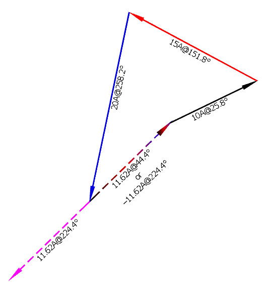
My answer was correct as posted. The equation was correct as posted. The vectors will plot correctly. Re-reading post 157 should clear that up for you.
 

mivey

Senior Member
Current sense as you are using it is embedded in the physics of the event.
...
My point remains that I do not have to adopt the positive-negative convention to obtain through calculation the unknown current "In".
...
can you tell me exactly where am I assigning a positive or negative (symbol) to a current variable?
...
The latter equation should be ?In=Ia+Ib+Ic.
Honestly, I'm not sure what your current point is. I don't understand your refusal to accept you can represent the same number using polar coordinates as you can using rectangular coordinates.

Using polar coordinates instead of rectangular coordinates does not mean you have not made a sense choice. Using a "+" or "-" symbol is the same as adding 180 degrees to an angle. It is a simple math concept.

For four wires tied to a node, you can not take three known current measurements in vector form and use them to calculate the fourth unknown current vector without adopting some current entering or leaving (current sense) convention. It is a simple math concept.

Saying the sense is embedded in the physics of the event does not mean you make no choices. The physics of the event are not the measurement of the event. Whether or not you made the initial choice of the way the voltages were measured, the way the currents were measured, or the choice of the representation of these measurements, you still have to adopt these choices, if you are engaged in the cognitive process.

If you contend that you are just a calculator that takes three numbers and adds them together, then you are not a cognitive being and I would agree you made no choice.

Let's get the formula you disagree with down to the simplest level:
With I1=10@55? and I2=10@55?
...I1........In
--->----[]---->---
Here you can say I1=In, or I1-In=0=10@55?-10@55?=10@55?+10@235?

With I1=10@55? and In=10@235?
...I1........In
--->----[]----<---
Here you can say I1+In=0=10@55?+10@235=10@55?-10@55?, or I1=-In

In the first example, the neutral current leaving is positive. The neutral current entering is negative or In_leaving@(angle)?=In_entering@(angle+180)?

In the second example, the neutral current entering is positive. The neutral current leaving is negative or In_entering@(angle)?=In_leaving@(angle+180)?

You have supported just about every version of these formulas at one time another through this thread so I'm not sure what your latest position is.

To quote you on KCL:
"You can't say "into" a node because that implies only currents entering and not any that are leaving."

"...I believe the most accurate translation is: The algebraic sum of current into any junction is zero."
 

Smart $

Esteemed Member
Location
Ohio
I simply forgot to include the reverse rotation. My corrected answer would be:
Using In+Ia+Ib+Ic=0, we sum the currents and multiply by -1 and In would be 11.62A with an angle of 44.36?
Using In=Ia+Ib+Ic, we sum the currents and In would be 11.62A with an angle of 224.4?

My answer was correct as posted. The equation was correct as posted. The vectors will plot correctly. Re-reading post 157 should clear that up for you.
Your 11.62A@224.4? is exactly why I have a problem with your method of adopting the positive-negative convention.

I could care less if you want to use the positive-negative convention. But in no way is 11.62A<224.4? the same as 11.62A<44.4?. They are opposing currents. To say a current is "not" entering a node by assigning a negative symbol to its value is one thing, but totally reversing its polarity is another.

plot.gif
 

mivey

Senior Member
Your 11.62A@224.4? is exactly why I have a problem with your method of adopting the positive-negative convention.

I could care less if you want to use the positive-negative convention. But in no way is 11.62A<224.4? the same as 11.62A<44.4?. They are opposing currents. To say a current is "not" entering a node by assigning a negative symbol to its value is one thing, but totally reversing its polarity is another.
But that's the point. I have not reversed the polarity. In that case I am calculating the current leaving the node. I labeled the current leaving the node on the neutral wire as "In". There is nothing that says you only have to calculate the current entering a node.

When you choose to calculate the current entering the node on the neutral, you have made a choice of sense. When you choose to calculate the current leaving the node on the neutral, you have made the opposite sense choice.

Saying the analysis was already set up a certain way does not mean you made no choice because you had to adopt the choice that was made before you got there.
 

Mayimbe

Senior Member
Location
Horsham, UK
Consider the graphic a single frame of a video (extremely high frame rate :D), i.e. as if the video was paused at that instant. When the video is in play mode, the axes (plural form of axis) remain stationary while the phasors (line with arrows) rotate counterclockwise about the origin at the rate of 3600 rpm (60Hz). Using Ia phase angle as 0? reference, t=123 the current of Line "a" is at its positive peak and thus aligned with the positive horizontal axis at 0?. The other phase currents are at +120? and -120?. They are not at their peak because the graph axes are horizontal is real, vertical is imaginary. To obtain the real value for the other two phasors, their tip has to be projected to the real (horizontal) axis.

When in motion, if we were to put pens at the projected-to-real-axis points of all three phasors and were to drag a piece of paper vertically under those pens, we would be plotting the waveforms associated with each current over time.

Yes, I knew that. But whats the point of saying that. Why do you need to know the real value of the current? If what the ammeter tells you is the rms value of the current, and through that you can get whatever you want, the real value and the imaginary value.

Yes. In the rotating phasor description above, we use the peak value as the length (magnitude) of the phasor. In a static phasor diagram, we use the rms value. This follows the purpose and the math involved. To use a rotating phasor "video", we are concerned with instantaneous values. Using a static phasor diagram the rms values are all we are concerned with.

So, for you, this instantaneous values are the real values of the current??
 

mivey

Senior Member
But that's the point. I have not reversed the polarity. In that case I am calculating the current leaving the node. I labeled the current leaving the node on the neutral wire as "In". There is nothing that says you only have to calculate the current entering a node.

When you choose to calculate the current entering the node on the neutral, you have made a choice of sense. When you choose to calculate the current leaving the node on the neutral, you have made the opposite sense choice.

Saying the analysis was already set up a certain way does not mean you made no choice because you had to adopt the choice that was made before you got there.
To put it another way:
Exercise #1
Given: A node has only four wires connected to it and the following three currents are measured entering the node: 10A@25.8?, 15A@151.8?, and 20A@258.2?
Find: The magnitude and angle of the current leaving the node on the forth wire.

Exercise #2
Given: A node has only four wires connected to it and the following three currents are measured entering the node: 10A@25.8?, 15A@151.8?, and 20A@258.2?
Find: The magnitude and angle of the current entering the node on the fourth wire.

Exercise #3
Given: A node has only four wires connected to it and the following three currents are measured leaving the node: 10A@25.8?, 15A@151.8?, and 20A@258.2?
Find: The magnitude and angle of the current leaving the node on the fourth wire.


Exercise #1 is an application of this KCL statement: The sum of the currents entering a junction of conductors is equal to the sum of the currents leaving the junction of conductors.

Exercise #2 is an application of this KCL statement: The sum of the currents entering a junction of conductors is zero at all times.

Exercise #3 is an application of this KCL statement: The sum of the currents leaving a junction of conductors is zero at all times.

All three applications are perfectly valid ways to analyze the circuit and your choice would depend on what you are after. You can choose to analyze it differently for different situations.
 

mivey

Senior Member
What you can't always solve is a question like this:
Given: A node has only four wires connected to it and the following three currents are measured: 10A@25.8?, 15A@151.8?, and 20A@258.2?
Find: The magnitude and angle of the current on the fourth wire.

You can't even be sure of just the magnitude alone.

For an example of why you can't, see post #145
 

Smart $

Esteemed Member
Location
Ohio
Honestly, I'm not sure what your current point is. I don't understand your refusal to accept you can represent the same number using polar coordinates as you can using rectangular coordinates.

Using polar coordinates instead of rectangular coordinates does not mean you have not made a sense choice. Using a "+" or "-" symbol is the same as adding 180 degrees to an angle. It is a simple math concept.

For four wires tied to a node, you can not take three known current measurements in vector form and use them to calculate the fourth unknown current vector without adopting some current entering or leaving (current sense) convention. It is a simple math concept.

Saying the sense is embedded in the physics of the event does not mean you make no choices. The physics of the event are not the measurement of the event. Whether or not you made the initial choice of the way the voltages were measured, the way the currents were measured, or the choice of the representation of these measurements, you still have to adopt these choices, if you are engaged in the cognitive process.

If you contend that you are just a calculator that takes three numbers and adds them together, then you are not a cognitive being and I would agree you made no choice.

Let's get the formula you disagree with down to the simplest level:
With I1=10@55? and I2=10@55?
...I1........In
--->----[]---->---
Here you can say I1=In, or I1-In=0=10@55?-10@55?=10@55?+10@235?

With I1=10@55? and In=10@235?
...I1........In
--->----[]----<---
Here you can say I1+In=0=10@55?+10@235=10@55?-10@55?, or I1=-In

In the first example, the neutral current leaving is positive. The neutral current entering is negative or In_leaving@(angle)?=In_entering@(angle+180)?

In the second example, the neutral current entering is positive. The neutral current leaving is negative or In_entering@(angle)?=In_leaving@(angle+180)?

You have supported just about every version of these formulas at one time another through this thread so I'm not sure what your latest position is.

To quote you on KCL:

But that's the point. I have not reversed the polarity. In that case I am calculating the current leaving the node. I labeled the current leaving the node on the neutral wire as "In". There is nothing that says you only have to calculate the current entering a node.

When you choose to calculate the current entering the node on the neutral, you have made a choice of sense. When you choose to calculate the current leaving the node on the neutral, you have made the opposite sense choice.

Saying the analysis was already set up a certain way does not mean you made no choice because you had to adopt the choice that was made before you got there.

I give up!!!!

No I am not conceding my position... I'm just getting a headache from all this and I have much better things to do, from my point of view.

Your position reminds me of, shall we call it a woman's prerogative... when she says yes but means no, when you are, by her reasoning, supposed to know it means no.
 

mivey

Senior Member
I give up!!!!

No I am not conceding my position... I'm just getting a headache from all this and I have much better things to do, from my point of view.

Your position reminds me of, shall we call it a woman's prerogative... when she says yes but means no, when you are, by her reasoning, supposed to know it means no.
:roll: Not sure about all that, but you are supposed to know how to use a tool before you use it. If someone is not sure of the proper way to apply the different statements of KCL, then I would suggest they not try to use them.
 

Smart $

Esteemed Member
Location
Ohio
Yes, I knew that. But whats the point of saying that. Why do you need to know the real value of the current? If what the ammeter tells you is the rms value of the current, and through that you can get whatever you want, the real value and the imaginary value.
Well it stemmed from mivey using so-called instantaneous currents as an example using non-zero-degree values.

So, for you, this instantaneous values are the real values of the current??
Well, technically real values are real values, and anything else is not. Yet I am quite comfortable using rms values for everything that doesn't require the use of instantaneous values.
 

roger

Moderator
Staff member
Location
Fl
Occupation
Retired Electrician
In the picture below, where is the start and finsh?

circle.jpg


;)


Roger
 
Status
Not open for further replies.
Top