3-phase transformers

Status
Not open for further replies.

gar

Senior Member
Location
Ann Arbor, Michigan
Occupation
EE
091207-2214 EST

Brian Oshman:

No way would you classify a source that has two separate single phase transformers fed with inputs 120 deg apart as a single phase center tapped transformer. Under these conditions it is a two or three phase source. You would not classify a transformer secondary as center tapped unless all the secondary winding was on the same core and the tap was at the midpoint of the secondary. You could roughly simulate a center tapped secondary with two separate single phase transformers with primaries connected in series or parallel so the secondary voltages were 180 deg out of phase.

A true three phase transformer has a common core with multiple center legs, one for each phase. It is not three single phase transformers in one container.
From "Electrical Circuits and Machinery", by Hehre and Harness, John Wiley, 1942.
Page 264 has a photo of a three-phase transformer. Also on this page
The three-phase transformer is slightly more efficient than three single-phase transformer, as there is less iron per kilowatt output, but the cost of upkeep and of spare units is greater. In sizes above 2000 kva and above 66,000 volts the three-phase transformer can be built somewhat more cheaply than three single-phase transformers totaling the same capacity,

.
 
You could roughly simulate a center tapped secondary with two separate single phase transformers with primaries connected in series or parallel so the secondary voltages were 180 deg out of phase.

Well there is the term I was looking for. I know that a center tap is really in the mid point of the winding but electrically it will simulate the same thing with two coils in series which essentially becomes one coil that has a tap midpoint. Physically it is not the same but electrically it is. This is why the transformer will run both single and three phase loads simultaneously.

I wasn't looking to split hairs. What it really is as pertained to the topic is a three phase WYE transformer that has gone bad and needs to be replaced. The rest is just theoretical banter. It was just to break it down as to why the voltages remain the same in the working portion, not to call it one thing or the other.
 

gar

Senior Member
Location
Ann Arbor, Michigan
Occupation
EE
091208-0805 EST

Brian:

Well there is the term I was looking for. I know that a center tap is really in the mid point of the winding but electrically it will simulate the same thing with two coils in series which essentially becomes one coil that has a tap midpoint. Physically it is not the same but electrically it is. This is why the transformer will run both single and three phase loads simultaneously.
Two separate coils connected together are not the same as a center tapped coil unless the magnetic flux coupling to the two coils is the same as that coupling to the single coil.

Consider two cases. Both use the same design criteria for the transformer.
First, two separate 5 KVA transformers each with a 120 V secondary. Measure the internal series impedance as viewed from the secondary.
Second, a single 10 KVA transformer with a center tapped 240 V secondary. Measure the internal series impedance as viewed from one 120 side of the output.
In the second case you will find a somewhat lower internal impedance.

Another consideration. Assume a very low impedance to the primary or primaries of the transformers. Meaning a change in load produces no change in the input voltage.

In the two transformer arrangement a load change on one transformer produces no voltage change at the output of the other transformer. This is because the common source impedance feeding the two transformers is essentially zero.

In the single transformer with center tapped secondary there is common impedance relating to the primary such that a load change on half of the secondary produces a voltage change on the other half of the secondary. The voltage change on the load change side is greater than the other side, although on the non-load changing side the change is less it exists and is significant (maybe about 1/3). A 10 V change on the load change side might produce a 3 V change on the non-change side. A 3 V change will produce a noticeable incandescent lamp flicker.

Conclusion: the two separate transformers vs a single center tapped secondary transformer are not electrically the same.

The original post used the word "Hypothetically", then went on to ask
My question is doesn’t the transformer (after C coil failure) electrically become a single-phase center-tapped transformer? If so, then the voltage would need to change, right? Would the voltage then become 104/208?
and the answer is no.

My goal here is not to be picky, but to provide a better understanding of the circuit.

.
 

scott thompson

Senior Member
What About...

What About...

Here is another view of this "A-B-N" Wye scenario;

Bring out Phases "A" + "B", along with the Conductor tapped at the Star Point (in this case, the Grounded Conductor "N") from a 3 Phase 4 Wire Wye Secondary.

One description of this Circuit would be a:
"1 Phase 3 Wire Multiwire Branch Circuit (or Feeder)"

Another description of this Circuit would be:
" 3 Phase 3 Wire Open Wye"

The "A-B-N" Circuit could be connected to the Primary side of an Open Wye / Open Delta Transformer setup, and derive a 3 Phase 3 Wire Delta, or 3 Phase 4 Wire Delta on the Secondary side.

Example:
The "A-B-N" Circuit is 208/120V (208V L-L, 120V L-N).

Circuit feeds an Open Wye x Open Delta Transformer setup, which consists of (2) separate Isolated Transformers (may be split coil windings on pri. + sec., or just single windings).

Primary Windings of Transformer configured / rated for 120V.

Primaries of both Transformers connected in Parallel, with one end of each Primary Winding (H2 from Trans #1, H1 from Trans. #2) connected to Line "N" ("N" is comon to both Primary Windings).

Secondary Windings connected in Parallel - to form an Open Delta configuration.

If a 4 Wire Delta is desired, Secondaries would be Split Coil (120x240V), with the Coils of each Transformer's Secondary connected in Series Adding (X2 to X3). One Transformer to have a "Tap" placed at the "X2-X3" jumper, so as to create a Center tapped Neutral Conductor.
That Conductor would be bonded to a G.E.S., and thus become the SDS's Grounded Conductor.

For a 3 Wire Grounded SDS (Corner Grounded Delta), bond the "Common" connection on the Secondary side to the G.E.S., identify it as Phase "B", and that will be the SDS's Grounded Conductor.

To create an Ungrounded 3 Phase 3 Wire Delta, eliminate the Main System Bonding Jumper between the G.E.S. and the Secondary side of the Transformer.

BTW, "G.E.S." = Grounding Electrode System.

Additionally, the Primary Circuit could be one of the following:

  • "A-B-N"
  • "B-C-N"
  • "A-C-N"


Just wanted to add my 2? via a semi off-topic post! ;)

Scott
 

mivey

Senior Member
El' Bump'o!!!

Any responses to the last post (open wye scenario)

Scott
Did you have a question?

An open-wye open-delta is a common configuration and it seems that is what you were describing. Not sure about your term "connected in parallel" but I assumed you were just talking about the standard open delta and wye connections. Were you proposing a non-standard connection?

FWIW, you can also have an open-wye to 4-wire wye connection.
 

LarryFine

Master Electrician Electric Contractor Richmond VA
Location
Henrico County, VA
Occupation
Electrical Contractor
Any responses to the last post (open wye scenario)
Okie-dokie!

Bring out Phases "A" + "B", along with the Conductor tapped at the Star Point (in this case, the Grounded Conductor "N") from a 3 Phase 4 Wire Wye Secondary.

The "A-B-N" Circuit could be connected to the Primary side of an Open Wye / Open Delta Transformer setup, and derive a 3 Phase 3 Wire Delta, or 3 Phase 4 Wire Delta on the Secondary side.
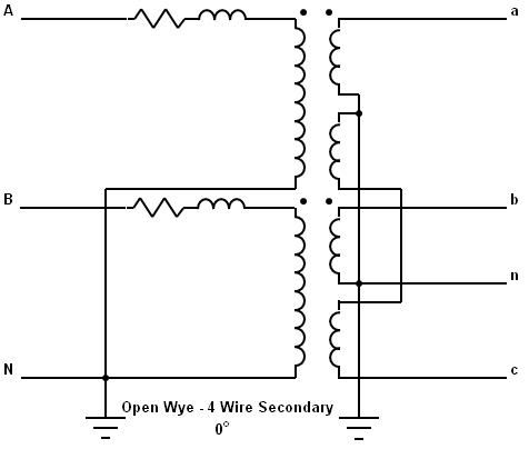
This is exactly how the POCO delivers open Deltas, which originated as 3ph modifications to existing 120/240v 1ph services. Note that the 120/240v section of a 4-wire open Delta is identical to a 120/240v 1ph service.

Example:
The "A-B-N" Circuit is 208/120V (208V L-L, 120V L-N).

Circuit feeds an Open Wye x Open Delta Transformer setup, which consists of (2) separate Isolated Transformers (may be split coil windings on pri. + sec., or just single windings).

Primary Windings of Transformer configured / rated for 120V.

Primaries of both Transformers connected in Parallel, with one end of each Primary Winding (H2 from Trans #1, H1 from Trans. #2) connected to Line "N" ("N" is comon to both Primary Windings).

Secondary Windings connected in Parallel - to form an Open Delta configuration.
These connections are nowhere near being parallel. At most, you could loosely say that the two secondaries of an open Delta are in series, with one conductor common to both.

However, with the timing difference, all there really is is two secondaries that share a common conductor. The rest of your commentary is, as Jor-el said, "Mere matters of fact."
 

scott thompson

Senior Member
Sorry guys, I thought this would be an interesting subject to discuss with other members - more specific, those members whom have not experienced non-standard Transformer configurations.

Kind of covering the way a "common" Grounded Conductor, derived from the Star Point of a Wye Configuration, differs greatly in operation (function) from the center tapped Grounded Conductor of a Single Phase system.

As to the differences in Open Wye and Open Delta Primary;

Open Delta Primary is lacking one Transformer (configuration is two single phase transformers), which may or may not utilize a Grounded Conductor at the Primary side (Phases "A", "B" and "C" will be fed to the Primary of the Open Delta Primary Transformer).
If the Primary Circuit contains a Grounded Conductor, this would derived from a Corner Grounded Delta.
The L-L Primary Voltage would match the Primary Winding Voltage, so Primary Feeder connections may be "rotated" without possibility of letting smoke out of Primary Windings.

Open Wye Primary is also lacking one Transformer (comprised of two - single phase transformers), but is almost always fed with a Grounded Conductor + two Ungrounded Conductors.
The Open Wye Primary is fed with the Common Conductor, derived from the Star point connection of the 3 Coil Windings of a 3 Phase Wye; and two of the three coil leads from the opposite ends of the three coils (AKA "Phase Lines").

The Common Conductor derived from the Star Point is normally Grounded, and thus is a system Grounded Conductor.

The Open Wye Primary Windings will have a Voltage rating of 57.7% the L-L Voltage (E-LL ?1.732), so therefore the Primary Feeders may be connected in only a single scheme, not in a "rotated" fashion, as was capable with the Open Delta Primary described previously.

To remove smoke from the Primary Windings on this Open Wye Transformer configuration:

1: Place the Common Conductor on an "Outside" Transformer Primary lead,

2: Connect one of the remaining two Primary Feeder conductors to the common termination between the two separate Transformers,

3: Connect the remaining Feeder to the "Outside" lead of the second Transformer,

4: Connect Feeders to a Polyphase Power Supply with ample Apparent Power.

Smoke will begin to emit from the Transformer with the Primary Winding connected L-L (the "Second" Transformer).

OALN...
The Open Wye Primary setups used by Utility Companies (Primary Distribution Feeders), are easy to identify - as they have no fuse in the common Grounded Conductor's Primary Termination.

I shall attempt to post more "meaty" material in the future.

BTW, Mivey:
How can a 4 Wire Wye Secondary (3 Transformers) derive from an Open Wye Primary (2 Transformers)???, or are you hinting towards driving an additional Transformer setup from the open delta secondary?

If you are referring to the connections schemes used for some smaller dry-type Polyphase Transformers (normally up to 15 KVA), which are rated 208/120V 3? 4 Wire - those are Open Delta Tee Transformers.

Sorry once again for posting a message, which clearly illustrates my lower intelligence / substandard cognition, and for producing "Mere matter of fact" discussion topics.
I will try harder to comply in the future.

Scott
 

mivey

Senior Member
BTW, Mivey:
How can a 4 Wire Wye Secondary (3 Transformers) derive from an Open Wye Primary (2 Transformers)
OpenWyeto4Wire.jpg


Sorry once again for posting a message, which clearly illustrates my lower intelligence / substandard cognition, and for producing "Mere matter of fact" discussion topics.
I will try harder to comply in the future.

Scott
I wouldn't say all that. It is just a common connection we see a lot and is considered a standard connection. This was common as far back as at least the 50's and probably much longer than that.

You posted the facts. I'm sure there are some here who had not seen it before but they made no comments and asked no questions.

You asked for comments and for myself, there was really nothing to add other than to say: That's the fact Jack! :grin:

Add: Don't mind us old fogies!
 
Last edited:

LarryFine

Master Electrician Electric Contractor Richmond VA
Location
Henrico County, VA
Occupation
Electrical Contractor
Sorry guys, I thought this would be an interesting subject to discuss with other members - more specific, those members whom have not experienced non-standard Transformer configurations.
No need for you or anyone else to apologize. You asked for comments, and got one. My post was in no way intended as a dressing down.

Kind of covering the way a "common" Grounded Conductor, derived from the Star Point of a Wye Configuration, differs greatly in operation (function) from the center tapped Grounded Conductor of a Single Phase system.
They do function somewhat similarly, but the best comparison is between the 120/240v 1ph transformer and the center-tapped transformer of an open or full Delta.

They are indeed identical, and the open Delta began as a modification to existing 1ph services, and continued as new services supplied from existing open-Delta transformer banks.

Few would request a high-leg Delta for a new service unless it was to supply an existing load, or to suit existing power-company equipment. Otherwise, a wye supply and service is standard.

As to the differences in Open Wye and Open Delta Primary;

Open Delta Primary is lacking one Transformer (configuration is two single phase transformers), which may or may not utilize a Grounded Conductor at the Primary side (Phases "A", "B" and "C" will be fed to the Primary of the Open Delta Primary Transformer).
It's rare for open Deltas to be supplied by all three phases, as it basically elimiates one of the open-Delta's benefits: requiring only two phases (and the system neutral, of course.)

Besides, I don't recall ever seeing primary distribution without a grounded conductor along for the ride. I can't imagine the power company leaving transformer cans floating.

Also, a Delta primary requires the use of double-ended (two HV bushings) primaries, which I rarely see in new transformer banks, although I see them quite a bit in older set-ups.

If the Primary Circuit contains a Grounded Conductor, this would derived from a Corner Grounded Delta.
The L-L Primary Voltage would match the Primary Winding Voltage, so Primary Feeder connections may be "rotated" without possibility of letting smoke out of Primary Windings.
You're describing any basic Delta set-up there.

Open Wye Primary is also lacking one Transformer (comprised of two - single phase transformers), but is almost always fed with a Grounded Conductor + two Ungrounded Conductors.
Absolutely.

The Open Wye Primary is fed with the Common Conductor, derived from the Star point connection of the 3 Coil Windings of a 3 Phase Wye; and two of the three coil leads from the opposite ends of the three coils (AKA "Phase Lines").

The Common Conductor derived from the Star Point is normally Grounded, and thus is a system Grounded Conductor.

The Open Wye Primary Windings will have a Voltage rating of 57.7% the L-L Voltage (E-LL ?1.732), so therefore the Primary Feeders may be connected in only a single scheme, not in a "rotated" fashion, as was capable with the Open Delta Primary described previously.

To remove smoke from the Primary Windings on this Open Wye Transformer configuration:

1: Place the Common Conductor on an "Outside" Transformer Primary lead,

2: Connect one of the remaining two Primary Feeder conductors to the common termination between the two separate Transformers,

3: Connect the remaining Feeder to the "Outside" lead of the second Transformer,

4: Connect Feeders to a Polyphase Power Supply with ample Apparent Power.

Smoke will begin to emit from the Transformer with the Primary Winding connected L-L (the "Second" Transformer).
No argument there. Let's not do that, though. ;)

OALN...
The Open Wye Primary setups used by Utility Companies (Primary Distribution Feeders), are easy to identify - as they have no fuse in the common Grounded Conductor's Primary Termination.
Plus, as I suggested earlier, the presence of single-bushing transformers.

I shall attempt to post more "meaty" material in the future.
"Where's the beef?!" :D
 

scott thompson

Senior Member
Mivey;

The Schematic in your latest reply is the Open Delta "TEE" configuration I had mentioned in the previous post.
Primary is Open Wye; Secondary is Open Delta TEE.

Schematic is somewhat crude, as it does not include tapped sections on the Secondary Windings.

FWIW, the Primary may also be configured as Open Delta "VEE" or "TEE", with the Secondary configured as 120\208V 3? 4 Wire Open Delta TEE.

Larry;

Typically when a Grounded Conductor is used with the Primary side Circuit, one could say the arrangement is an Open Wye - unless the Primary Feeder is derived from a 3 Phase 3 Wire Corner Grounded Delta.

--- for Two Transformer Arrangements ---

If Primary Circuit has (2) of (3) "Phases", and the 3rd conductor is the common from the "Star Point" of a 4 Wire Wye, the Primary arrangement is Open Wye.
Still is 3? 3 Wire, but is Open Wye, not Open Delta Vee or Tee.

If Primary Circuit has all 3 "Phases" brought to the Primary, the Primary arrangement is Open Delta - either Vee (most common), or Tee.

Your description of the Pole Mounted Transformers having single bushings (and most likely only one fuse link per Transformer - two transformers total), kind of points to an Open Wye Primary.
The Primary Distribution Circuit would be 12470Y\7200V 3? 4 Wire Wye, and the Primary Windings of the two transformers would be 7200V.
These may also be MGCN (Multi Grounded Common Neutral) Systems.

In my area, the normal connections for two-transformer pole mounted arrangements are Open Delta Vee on both sides (Primary and Secondary).
Primary side is 12470V L-L-L (A, B & C) with fuse links on all 3 lines.
Secondaries may be 3 Wire or 4 Wire; 3 Wire flavors include 240V, 480V, 600V, Corner Grounded, Center Tap Grounded (Grounded at Pole only), and Ungrounded.

Utility Companies in my area do not use MGCN configs, nor utilize a Grounded Conductor for Polyphase Transformer setups, which accounts for the lack of Open Wye Primaries.

Thanks to both of you for the responses.

Scott
 

Cold Fusion

Senior Member
Location
way north
...FWIW, the Primary may also be configured as Open Delta "VEE" or "TEE", with the Secondary configured as 120\208V 3? 4 Wire Open Delta TEE....
scott -
I don't think I've ever seen a "Secondary configured as 120\208V 3? 4 Wire Open Delta TEE". Could you post a sketch or a link, showing the connections and vector relationships?

cf
 

mivey

Senior Member
Mivey;

The Schematic in your latest reply is the Open Delta "TEE" configuration I had mentioned in the previous post.
Primary is Open Wye; Secondary is Open Delta TEE.

Schematic is somewhat crude, as it does not include tapped sections on the Secondary Windings.

FWIW, the Primary may also be configured as Open Delta "VEE" or "TEE", with the Secondary configured as 120\208V 3? 4 Wire Open Delta TEE.
Nope. You are completely off track. Look at the diagram and more closely. When trying to analyze a transformer connection, it is helpful to actually assign some voltages and follow the connections.

You will find it helpful to pick common voltages and common angles to make it easier to follow. No need to complicate the issue with complicated numbers. When making the analysis, assume that the transformer ratio is 1:1. By that I mean that the voltage across the primary coil is the same as the voltage across the secondary coil.

You will also find it much easier to assume a perfect transformation and leave off the transformer impedances. The transformer has a core made of a material with high permeability. This allows a more efficient way to carry the flux from the primary coil to the secondary coil. In magnetic circuits, the flow of flux in the core is analgous to the flow of current in electrical circuits.

When the flux flows, losses occur in the core. There are eddy losses and hysteresis losses. The flux in the transfomer reverse in cycles. The resistance to this reversal in flux is a simple way to describe the hysteresis loss. It is reduced by making improvements in the properties of the core material.

Eddy currents circulating in the transformer contribute to the eddy losses and is reduced by reducing the thickness of the core laminations. That is because the eddy currents are caused by the flow of magnetic flux normal to the width of the core. A solid core transformer would have much higher losses and that is why we use cores laminated from very thin sheets. The eddy loss is a function of the square of the width of the core lamination, times the square of the flux density, times a constant. The losses are modeled by parallel and series impedances in the transformer circuit.

In addition to the capital costs, the cost of losses must be considered when evaluating the cost of owning a transformer so we include calculations to evaluate the cost of load losses, no-load losses, and stray losses.

Although the cost of these losses must be considered when evaluating the economics or for more complex engineering calculations, we can exclude them for the purposes of studying the transformer connections and comparing the primary system voltages and secondary system voltages.

Be sure when following the connections that you do not simply add or subtract the magnitudes of the voltages. That is what you would do for scalar numbers located on a one-dimensional number line. The voltages we are looking at here are represented by two dimensional numbers.

Most of the time we see those numbers using a polar coordinates. To add and subtract, it is easier to convert those into rectangular coordinates.

In converting to rectangular coordinates, the current and angles use polar coordinates to represent a number located in two dimensions. For rectangular coordinates, Ia@A? = Xa+jYa where X is a scalar (or single dimensional) number on the horizontal axis and Y is a scalar number on the vertical axis. This gives you two one-dimensional numbers that can be added and subtracted separately. The "j" is used to indicate the vertical axis (also known as the imaginary axis). "X+jY" is the complex number representation of a two-dimensional number.

Example:
Ia@A?: Xa = Ia*cos(A?), Ya = Ia*sin(A?)
Ib@B?: Xb = Ib*cos(B?), Yb = Ib*sin(B?)
Ic@C?: Xc = Ic*cos(C?), Yc = Ic*sin(C?)

Xsum = Xa+Xb+Xc
Ysum = Ya+Yb+Yc

This gives you the complex number "Xsum+jYsum".

You can convert Xsum+jYsum to polar coordinates using a calculator or in several steps. The magnitude (denoted by using pairs of "|" symbols) is given by the square root of the sum of the squares: |Xsum+jYsum| = sqrt(Xsum^2 + Ysum^2).

The angle is given by the inverse tan (or arctan) of Ysum/Xsum. This is a little more complicated if your calculator does not directly convert to polar coordinates because you must account for what quadrant of the two-dimensional polar plane you are in. A calculator that does not handle complex math will usually give angles from +90 to -90 degrees and you will have to make the angle correction yourself using the following information:

The polar quadrants:
................90?(+Y)
.................|
.............II..|..I
.................|
(-X)180?---------|--------0?(+X)
.................|
............III..|..IV
.................|
.................|
................270?(-Y)

For different signs of X & Y, you will be in different quadrants:
+X & +Y = 1st quadrant
-X & +Y = 2nd quadrant
-X & -Y = 3rd quadrant
+X & -Y = 4th quadrant

Tan is positive in the 1st and 3rd quadrant and negative in the 2nd and 4th quadrant. When you take the arctan (arctangent) of a number, you will usually be given a positive or negative angle of less than 90 degrees (the 1st or 4th quadrant). That means for a -X & +Y (2nd quadrant), your angle result will be in the 4th quadrant so you will have to add 180 degrees to get the result to the 2nd quadrant. The same is true for -X & -Y (3rd quadrant). So to get the correct angle, you have:
1st Q with +X & +Y = arctan[(+Y)/(+X)] = XY?
2nd Q with -X & +Y = arctan[(+Y)/(-X)] + 180? = XY?
3rd Q with -X & -Y = arctan[(-Y)/(-X)] + 180? = XY?
4th Q with +X & -Y = arctan[(-Y)/(+X)] = XY?

Combining the magnitude and angle, you will now have |Xsum+jYsum|@XY?
 

mivey

Senior Member
It's rare for open Deltas to be supplied by all three phases, as it basically elimiates one of the open-Delta's benefits: requiring only two phases (and the system neutral, of course.)

Besides, I don't recall ever seeing primary distribution without a grounded conductor along for the ride. I can't imagine the power company leaving transformer cans floating.
Well, they can as it is a common utility connection. The benefit here is saving a pot. Also, open-delta to open-delta might not have a ground on the secondary center-tap.

For the case where you have two phases, we normally use open wye primary.
 

gar

Senior Member
Location
Ann Arbor, Michigan
Occupation
EE
100122-1306 EST

Larry:

In photo P4 is shown the supply to my house. The primary side is 3 phase and no ground. What it is at the substation I do not know, probably a Y to a establish a reference to earth. But there is no ground wire with the three phase wires. By looking at the various photos, after some study, it is moderately clear there are only 3 wires from the substation. Anywhere else in our DTE area where there is Y distribution you can find a primary with 3 hot wires and a fourth wire for ground. In the subdivisions supplied by a Y there are only two wires, single post transformers are used, and the neutral wire may not be immediately obvious. There are many subdivisions in the DTE area with 3 phase primary and no ground wire.

http://beta-a2.com/misc_TMP_photos.html

Of course in this case I have single phase off of one phase. If I wanted three phase it probably would not be costly.

At the shop we have a 3 phase Y primary feeding two transformers, and an open delta on the secondary side.

.
 
Last edited:

scott thompson

Senior Member
Cold Fusion:

scott -
I don't think I've ever seen a "Secondary configured as 120\208V 3? 4 Wire Open Delta TEE". Could you post a sketch or a link, showing the connections and vector relationships?

Here is an older Schematic I have posted at ECN, which describes the Open Delta TEE, with 120/208V 3 Phase 4 Wire Secondary:

185.gif


Sorry, no Vector Diagrams available...

Mivey:

How about these Transformer Schematics... Want to toss some numbers to these? ;)

186.gif


187.gif


188.gif


I have more Drawings compiled - most are still AutoCAD .DWG files, however, around 20% have been Exported + converted to a web-friendly Raster format (.GIF, .JPG, .PNG, etc.).
These Graphics have been uploaded to ECN.

Scott
 

gar

Senior Member
Location
Ann Arbor, Michigan
Occupation
EE
100127-0852 EST

Scott:

Your last drawing will produce about 0 V out, not 480 V.

As drawn the secondary subtracts from the primary. Swap X1 and X4 and you will get 480.

.
 

mivey

Senior Member
Mivey:

How about these Transformer Schematics... Want to toss some numbers to these? ;)
I don't need the exercise, but if you think it is something that will help you, I'll be glad to do it. But, it would probably be more useful to you if you gave it a shot first.
 
Status
Not open for further replies.
Top