2-phase, 5-wire Thank You!

Status
Not open for further replies.

LarryFine

Master Electrician Electric Contractor Richmond VA
Location
Henrico County, VA
Occupation
Electrical Contractor
agreed....I had never seen or heard of a 2-phase service either. But they do still have some on the east coast apparently....this one was in philadelphia. They derive it on the utility side using multiple transformers with different tap settings (something to do with "more economically advantageous" back in the day = less transformers needed).
You might be looking at open-Delta supplies, too.
 

adelle

Member
Two phase principles are not exactly dead. Most (probably all) single phase induction motors operate on the same principles as a two phase motor. You have at least two sets of windings with the voltage and current in each out of phase with the other(s) to create a rotating field. If the voltage and current in each set of windings were in phase with each other, the rotor would never develop any torque.

And stepper motors are still two phase. But as they are mostly powered from electronic devices, making the two phases is done electronically.
 

AdrianWint

Senior Member
Location
Midlands, UK
In the UK we use Scott transformers for traction.

Its an ideal solution to the problem of how to power a section of electrified rail road track (ie. an upline & a down line) from a three phase supply while trying to keep the load reasonably balanced.

I also understand that the channel tunnel uses Scott transformers in this way to dervive the 25kV traction supply.

Adrian
 
Were any western cities wired for 2-phase? In Butte Montana I saw a series of overhead lines that were four across, all the same size on similar insulators. Probably between 2 and 6kv. OTOH, most of the mines in the area seemed to be 3-phase.
 

jim dungar

Moderator
Staff member
Location
Wisconsin
Occupation
PE (Retired) - Power Systems
Were any western cities wired for 2-phase? In Butte Montana I saw a series of overhead lines that were four across, all the same size on similar insulators. Probably between 2 and 6kv. OTOH, most of the mines in the area seemed to be 3-phase.
2-phase was most popular in the East coast area, partly because the first generators at Niagara Falls, and the resulting distribution were 2-phase.
 

kwired

Electron manager
Location
NE Nebraska
Were any western cities wired for 2-phase? In Butte Montana I saw a series of overhead lines that were four across, all the same size on similar insulators. Probably between 2 and 6kv. OTOH, most of the mines in the area seemed to be 3-phase.

sounds like three phase conductors and one grounded conductor - 3 phase 4 wire.
 

rattus

Senior Member
All overhead conductors I've seen are attached to insulators including the neutral. Probably done more for a method of attachment than for insulating purposes

In my neighborhood, three hots are run on crossarms with the neutral/ground tied to the poles with no insulators. Can't believe they would waste money on insulators that were not needed.
 

kwired

Electron manager
Location
NE Nebraska
In my neighborhood, three hots are run on crossarms with the neutral/ground tied to the poles with no insulators. Can't believe they would waste money on insulators that were not needed.

what are they tied with? they need some type of protection from abrasion against the pole, it will rub through over time.
 
Would the neutral be run on insulators though?

Neutral? You don't usually have a neutral on the primary distribution side. (These are on the "top of the pole" cross-arm, four wires, equally spaced, on identical insulators. There was 120/208 distribution lower on the pole.)

My first thought was "Hmm, 2-phase??", but I somehow doubt it, unless it was 120 years old.
 

rattus

Senior Member
That's one for me!

That's one for me!

what are they tied with? they need some type of protection from abrasion against the pole, it will rub through over time.

After looking more closely, I see that the neutral is carried on insulators along with the two legs of the 120V/240V service.
 

glene77is

Senior Member
Location
Memphis, TN
Just connect the CTs of the 2-phase secondaries. This config has been called 4-phase, but that would start another long winded discussion so don't blab it around!. The CT is the neutral.

Rattus,
You have piqued my interest.
Need to do some reading on 4ph, 5ph, 6ph, etc.,
and I think I see an upcoming application problem with inverted phases.
Don't answer this. Not part of this thread.
Thanks.
 

mivey

Senior Member
Neutral? You don't usually have a neutral on the primary distribution side.
You do for a wye distribution
(These are on the "top of the pole" cross-arm, four wires, equally spaced, on identical insulators.
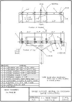
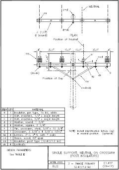
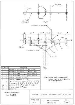
The neutral can be run on a pin on the cross arms along with the ungrounded conductors. With the lower voltages (like the 2kV or so you mentioned) you might not notice a difference in the pin insulators but it can become obvious with 12 & 25 kV distribution. It is sure obvious when they use post insulators for the ungrounded conductor and a pin insulator for the grounded conductor. See the C1.41, C1.41L, & C1.41P assemblies on pages 124, 125, & 126 of (warning: a 12.6MB file)
http://www.usda.gov/rus/electric/pubs/1728f-804.pdf

C1-41Assembly.jpg

C1-41LAssembly.jpg

C1-41PAssembly.jpg
 

mivey

Senior Member
Wouldn't that be 5-wire?

Don't count too well on a Sunday. The answer is yes, the secondaries are not connected. There is no common conductor. There could be a reason for this, but I am too young to know what it might be. Have only seen it in books too.

3-wire 2-phase: The two phases are tied at the end-points of their windings. Used to reduce the amount of copper needed, but the common current was 1.41 times the phase currents (for balanced loads, otherwise the sqrt of the sum of the squares for the general case) and you had to allow for the higher voltage drop. It was more commonly used where motor loads were predominant. Can be viewed as two single-phase two-wire circuits sharing a common conductor.

4-wire 2-phase: The two phases are independent of each other (two single-phase two-wire circuits).

5-wire 2-phase: Two phases are tied at the mid-point of their windings (common configuration), or you could center-tap both windings on the 3-wire configuration. Used for the versatility of having higher and lower voltages available as well as being able to supply 2-wire and 3-wire single-phase loads. Can be viewed as two single-phase three-wire circuits sharing a common conductor.
 

rattus

Senior Member
3-wire 2-phase: The two phases are tied at the end-points of their windings. Used to reduce the amount of copper needed, but the common current was 1.41 times the phase currents (for balanced loads, otherwise the sqrt of the sum of the squares for the general case) and you had to allow for the higher voltage drop. It was more commonly used where motor loads were predominant. Can be viewed as two single-phase two-wire circuits sharing a common conductor.

4-wire 2-phase: The two phases are independent of each other (two single-phase two-wire circuits).

5-wire 2-phase: Two phases are tied at the mid-point of their windings (common configuration), or you could center-tap both windings on the 3-wire configuration. Used for the versatility of having higher and lower voltages available as well as being able to supply 2-wire and 3-wire single-phase loads. Can be viewed as two single-phase three-wire circuits sharing a common conductor.

Right you are!

My response was to the 4-wire question which got lost somewhere.
 
Status
Not open for further replies.
Top