Broken Delta Questions

Status
Not open for further replies.

big john

Senior Member
Location
Portland, ME
We have a bunch of ungrounded 600V systems. The only ground detection we have on them is some high-voltage wye-connected neon lamps.

I'm looking to install a broken-delta transformer so I can operate a ground detection relay. I'll be making it out of three 600:120 transformers; solidly grounded wye-connected primary; ungrounded open-delta secondary with a burden resistor.

My questions:

I'd like to keep some sort of indicator lamp scheme to see what phase has the fault, but I don't want them connected to the 600V primary. I've seen a diagram where each ground-fault lamp was connected in parallel with one of the secondary windings of the broken delta. Would that work? Would they still operate in the same fashion that they do now? (And if so, how?)

Also, I'm 99% sure that during a ground fault, the maximum voltage across the break in my delta will be 120V. I'm having trouble understanding why, though, and vector math doesn't mean much to me. Any help there?

Thanks a bunch.

-John
 

mivey

Senior Member
The maximum voltage will be 3 times the L-N voltage. The secondaries will be connected in series. Pick your ratio so you will get
V_relay / 3 / V_primary_L-N = V_sec / V_Pri = transformer ratio
 

mivey

Senior Member
I'm having trouble understanding why, though, and vector math doesn't mean much to me. Any help there?
Vector math tells you why. I was trying to find a good picture but draw your triangle and shift the reference point from the centroid to one of the corners (one conductor becomes grounded) and you will shift the voltage reference. Instead of the two un-grounded primaries having L-N voltage, they now will have L-L voltage. The result is that you will have double the following value (summing the open delta): sqrt(3)*V_LN*cos30? which is equal to 3*V_LN.

There is a brief explanation of what happens at the bottom of page 4 here: http://www.electricalmanuals.net/files/RELAYS/GE/IFV/GEK-49886A- .pdf
 

Smart $

Esteemed Member
Location
Ohio
The maximum voltage will be 3 times the L-N voltage. The secondaries will be connected in series. Pick your ratio so you will get
V_relay / 3 / V_primary_L-N = V_sec / V_Pri = transformer ratio
I don't see it... How is the maximum voltage 3 times the L-N voltage? I see the L-N voltage as 600V/√3 = 346.4V under nominal conditions. When there is a single ground fault, the primary connected to the faulted phase primary goes to 0V while the other two go to 600V.
 

mivey

Senior Member
I've seen a diagram where each ground-fault lamp was connected in parallel with one of the secondary windings of the broken delta. Would that work? Would they still operate in the same fashion that they do now? (And if so, how?)
I can't find a diagram right now but again, shift the corner of the triangle to ground. One primary will have the same potential on both sides of the coil and will not light the lamp on the secondary side. The other two lamps will have a higher voltage (the reference moved from the centroid of the triangle to the corner) and will get brighter.
 

mivey

Senior Member
I don't see it... How is the maximum voltage 3 times the L-N voltage? I see the L-N voltage as 600V/√3 = 346.4V under nominal conditions. When there is a single ground fault, the primary connected to the faulted phase primary goes to 0V while the other two go to 600V.
You are good with diagrams, perhaps you could draw it out and help the OP as I can't put my hands on a good picture. Remember we are summing the secondaries. Once you draw it out it should be quite clear.

Add: You should wind up adding two segments. Say if the triangle had the point up top and the top was grounded. You would add 600@240? + 600@300? to get 1039.23@-90? = 3 * 346.41
 
Last edited:

Smart $

Esteemed Member
Location
Ohio
You are good with diagrams, perhaps you could draw it out and help the OP as I can't put my hands on a good picture. Remember we are summing the secondaries. Once you draw it out it should be quite clear.
OK... you were referring to 3 times the nominal condition voltage of the secondaries.

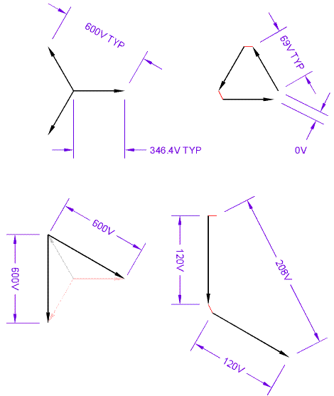
The simple explanation is under nominal conditions (NC) we have a wye-delta configuration and open the delta at one corner to measure the summed voltage of zero under nominal conditions. When one Line faults to ground, the primaries become open-delta configured with a voltage increase ratio of √3 (e.g. 346.4 to 600V) on each primary. The change from wye to open-delta of the primary results with the secondary being open-wye configured regarding the two secondaries having non-zero voltage. These two secondaries also see their voltage increase by a factor of √3, and being open-wye configured, sum to 3 times their nominal condition voltage.
 

big john

Senior Member
Location
Portland, ME
I follow some of this. I know that when a primary phase faults to ground, the other two phases read 600 volts to ground. Which happens to be 347*√3. That makes sense.

On my secondary side is where I get confused. If my L-L voltages don't change on the primary, why should they change on the secondary? And if I don't have a ground-reference on the secondary, how would the secondary know that any voltage change had occurred at all?

I'm gonna try a couple of vectors and see if maybe it will help me better understand the answers y'all have given so far. Thanks!

-John
 

gar

Senior Member
Location
Ann Arbor, Michigan
Occupation
EE
101107-2129 EST

Here is my simple analysis.

Three 120 V secondaries are in series. Phase angles 120 deg apart when the primaries are balanced and the output voltage of each secondary is about 69 V. The vector sum adds to 0.

Produce a grounded fault on one leg of the primary. This effectively removes the one monitoring transformer whose primary is shorted out.

Two transformers remain, each with 600 V on its primary. The result is two 120 V outputs added together. The phase difference between the two is 120 deg. Thus the output voltage is 120 V.

A ground fault on the primary side produces a change from 0 V out of the detector to 120 V.

.
 

mivey

Senior Member
101107-2129 EST

Here is my simple analysis.

Three 120 V secondaries are in series. Phase angles 120 deg apart when the primaries are balanced and the output voltage of each secondary is about 69 V. The vector sum adds to 0.

Produce a grounded fault on one leg of the primary. This effectively removes the one monitoring transformer whose primary is shorted out.

Two transformers remain, each with 600 V on its primary. The result is two 120 V outputs added together. The phase difference between the two is 120 deg. Thus the output voltage is 120 V.

A ground fault on the primary side produces a change from 0 V out of the detector to 120 V.

.
Should be 208 volts
 

mivey

Senior Member
I follow some of this. I know that when a primary phase faults to ground, the other two phases read 600 volts to ground. Which happens to be 347*√3. That makes sense.

On my secondary side is where I get confused. If my L-L voltages don't change on the primary, why should they change on the secondary? And if I don't have a ground-reference on the secondary, how would the secondary know that any voltage change had occurred at all?

I'm gonna try a couple of vectors and see if maybe it will help me better understand the answers y'all have given so far. Thanks!

-John
Your system L-L voltage does not change. What changes is the voltage across the primary coil. The primary coil is not connected L-L. It is connected to ground. This ground point is initially floating at the natural neutral point.

When ground becomes the same as one of the one of the "L"s (a fault), you have the system L-L voltage across the primary coil because the ground point moved from the middle of the system triangle to one of its corners. You now have L-L voltage across the primary coil instead of L-N voltage. In other words, we normally expect L-G and L-N to be the same and they will be for balanced, ungrounded, unfaulted conditions. During a fault on the ungrounded delta system, L-G becomes L-L.

Just remember that the secondary coil and primary coil are joined at the hip. Whatever voltage is impressed across the primary coil gets impressed across the secondary at some percentage. How these secondary voltages are joined together is the key. In my example to Smart, the voltage seen at the secondary is 1039.23@-90? * 120/600 or 208 volts. 208 will be the maximum voltage for your setup.
 

Smart $

Esteemed Member
Location
Ohio
Your system L-L voltage does not change. What changes is the voltage across the primary coil. The primary coil is not connected L-L. It is connected to ground. This ground point is initially floating at the natural neutral point.

When ground becomes the same as one of the one of the "L"s (a fault), you have the system L-L voltage across the primary coil because the ground point moved from the middle of the system triangle to one of its corners. You now have L-L voltage across the primary coil instead of L-N voltage. In other words, we normally expect L-G and L-N to be the same and they will be for balanced, ungrounded, unfaulted conditions. During a fault on the ungrounded delta system, L-G becomes L-L.

Just remember that the secondary coil and primary coil are joined at the hip. Whatever voltage is impressed across the primary coil gets impressed across the secondary at some percentage. How these secondary voltages are joined together is the key. In my example to Smart, the voltage seen at the secondary is 1039.23@-90? * 120/600 or 208 volts. 208 will be the maximum voltage for your setup.
Not only does the voltage magnitude change on a ground fault... so does the phase angle. In the following depiction, under nominal conditions using 600:120 xfmrs, the top left voltage diagram represents the primary and to its right is the secondary. Under a single fault condition the lower left diagram represents the primary and to its right is the secondary.

BrokenDeltatopic.gif
 

nollij

Member
Location
Washington
There will be no potential change over the primary windings of the faulted phase. This will result in no potential over the secondary windings of that phase. The summation over all three phases on the secondary (with one set of windings with 0 potential) will have a magnitude of 1.0pu (L-N).

You need to specify that 600V primary system is a L-L value. You also need to specify that each transformer is 600:120 or 5:1 ratio and the 600 is not the L-L value as you are connecting 3 transformers in a Wye primary connection. Your system description is incomplete and I feel what may be leading people to be confused.

If the transformers are a 5:1 ratio, and the system primary line to line voltage is 600V, and the single phase transformers are connected in a Wye primary configuration, and the secondary of the transformers are connected in a broken delta configuration, and one of the phases are faulted:

There will be ~70 volts over the summation of the broken delta.

The lamp scheme would work if the system is setup as described.
 

SG-1

Senior Member
In a medium voltage setting a resistor is used in parallel with the relay to prevent ferro-resonance, because of the system capitance & the L-G transformer configuration.

I do not know if this would be necessary at the 600V level.

Also the L-G transformers must be able to handle full L-L voltage, because when the first line goes to ground the L-G transformers will see the L-L voltage, because ground reference just became one line.
 

Smart $

Esteemed Member
Location
Ohio
...

I'd like to keep some sort of indicator lamp scheme to see what phase has the fault, but I don't want them connected to the 600V primary. I've seen a diagram where each ground-fault lamp was connected in parallel with one of the secondary windings of the broken delta. Would that work? Would they still operate in the same fashion that they do now? (And if so, how?)

...
Consider that under nominal conditions each secondary voltage will be 58% of the single-ground-fault-condition voltage. If using neon lamps connected parallel to each secondary winding, the strike voltage of the lamp must be lower than this 58% value in order for it to glow during nominal conditions.

Lamps connected parallel to each secondary winding will indicate similarly to the fashion they do now. Under nominal conditions they should each glow dimmly. Under a single-ground-fault condition, two should glow bright while one would be dark, indicating the grounded line.
 

Smart $

Esteemed Member
Location
Ohio
...

If the transformers are a 5:1 ratio, and the system primary line to line voltage is 600V, and the single phase transformers are connected in a Wye primary configuration, and the secondary of the transformers are connected in a broken delta configuration, and one of the phases are faulted:

There will be ~70 volts over the summation of the broken delta.

...

Here is the actual math. I think it is right this time.

...
Review your premise...

Under single-ground-fault condition, the broken-delta voltage with 5:1 xfmrs would be 208V.

Under nominal conditions, there would be ~69V across each secondary, but the sum, which is measured across the delta break, would be 0V.
 
Status
Not open for further replies.
Top