
Angel Electric
Member
- Location
- OBX, NC.
Flow switch for a sprinkler system riser. Which is correct N/O or N/C?
A Fellow fire tech explained to me that the contacts are open with a risistor in line ... When water flows the flow switch closes and it shunts the data circuit causing the fire alarm panel to go into Alarm, I guess im just going for second perspective of how the switch works and its purpose in what it is controling.?
I haven't done much fire alarm in recent years but in the old days a water flow switch as an initiation device would be wired N/O with a resistor across the contacts. Water flow would close the switch, shunt the resistor and send the system into an alarm condition. If the wiring became broken or a wire came off of a terminal then the FACP would read no resistance and would show a trouble alarm. This may all have changed now with addressable devices.
If the wire became broken or came loose from a terminal, the FACP would read infinite resistance and show a trouble. No resistance across the waterflow contacts would be an alarm (not a trouble), regardless of whether the system used traditional zone cards or addressable modules.
I've found it helpful to steer clear of the phrase 'trouble alarm'. Trouble signal or trouble condition leads to less confusion in my opinion.
I've found it helpful to steer clear of the phrase 'trouble alarm'. Trouble signal or trouble condition leads to less confusion in my opinion.
Flow switch for a sprinkler system riser. Which is correct N/O or N/C?
We must also realize that not all areas of the country require a monitored alarm system with a sprinkled building, here it is common to find the N.O. contacts used to turn on a simple 120 volt horn mounted on the outside of the building, and maybe one inside.
The flow switch, pressure switch/clapper switch (Dry system) and valve tamper switch's are also wired in parallel to sound these same horns.
Do you guys do a lot of riser rooms without engineered drawings?
For us all of this will be clearly spelled out on the fire alarm details and we are expected to follow them.
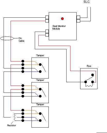
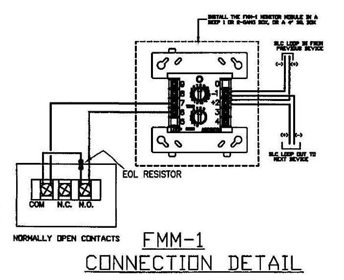
Here is a typical detail off a recent print
Woe be unto him who installs single gang boxes per your detail expecting the FMM-1 monitor module to fit.