How does thumper gnd detection work

Status
Not open for further replies.

tankfarms

Member
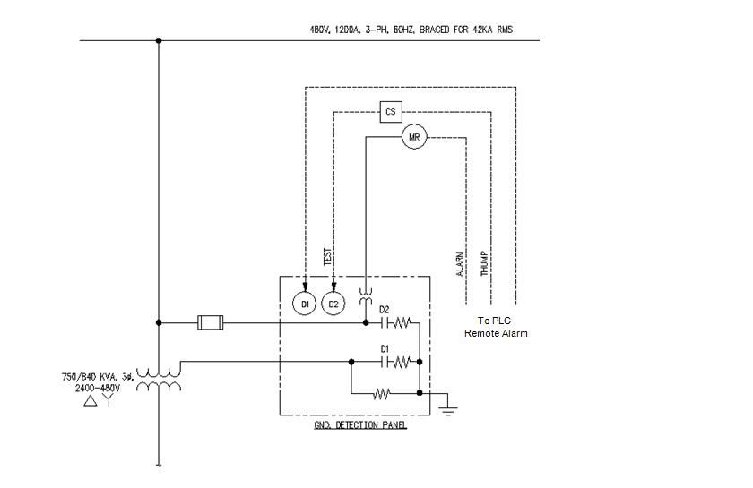
I recently got chance to work with various ground detection circuits. I have a Delta-Wye transformer as shown in the schematic below with wye ungrounded. Could someone explain how this circuit work and what each component does? In the MCC, I have seenthe gnd detection has meter relay (I assume that's the MR) with "Thumper-OFF-Test" poisition switches.

ThumperGnd.jpg
 

rcwilson

Senior Member
Location
Redmond, WA
Many high resistance ground systems have a fault locating function that varies the fault current in an on-off-on-off sequence that can be detected by a clamp-on ammeter. When turned on, the pulser, or thumper, cuts out part of the grounding resistor to increase the fault current from say 5 amps to 10 amps about 1 or 2 times a second.

The 5-10 amp ground fault current is going out on one of the phase wires and returning through the grounding/bonding system. An ammeter clamped around all three phase conductors on the faulted circuit will indicate the pulsing current. Most of the time you can detect the pulsing current by clamping on the outgoing conduit and follow the circuit to the fault location.

This fault locating without turning off the loads is one advantage of high resistance grounding. Clamp on meters with large jaws to fit around large conduits and feeders are available from the Hi-Res grounding suppliers.

(I can't read your schematic, so I may have the wrong description. "Thumper" usually refers to a high voltage underground fault locating method that pulses a large voltage on the faulted circuit. The arcing at the fault location makes an audible thump that can be felt at the surface and detected with listening/locating equipment. It is considered a destructive test that stresses the rest of the circuit.)
 

tankfarms

Member
Many high resistance ground systems have a fault locating function that varies the fault current in an on-off-on-off sequence that can be detected by a clamp-on ammeter. When turned on, the pulser, or thumper, cuts out part of the grounding resistor to increase the fault current from say 5 amps to 10 amps about 1 or 2 times a second.

The 5-10 amp ground fault current is going out on one of the phase wires and returning through the grounding/bonding system. An ammeter clamped around all three phase conductors on the faulted circuit will indicate the pulsing current. Most of the time you can detect the pulsing current by clamping on the outgoing conduit and follow the circuit to the fault location.

This fault locating without turning off the loads is one advantage of high resistance grounding. Clamp on meters with large jaws to fit around large conduits and feeders are available from the Hi-Res grounding suppliers.

(I can't read your schematic, so I may have the wrong description. "Thumper" usually refers to a high voltage underground fault locating method that pulses a large voltage on the faulted circuit. The arcing at the fault location makes an audible thump that can be felt at the surface and detected with listening/locating equipment. It is considered a destructive test that stresses the rest of the circuit.)


Do you mean my picture(schematic) is not actually displayed?
 

hurk27

Senior Member
Do you mean my picture(schematic) is not actually displayed?

It is displayed fine, some computers might have the display images turned off in IE under properties/advance, or in the forum settings, images can slow down a web page from loading allot if you have a slow Internet connection so sometimes these are shut off to speed up browsing, I'll try to find the settings and show you how to turn them on.
 

hurk27

Senior Member
Many high resistance ground systems have a fault locating function that varies the fault current in an on-off-on-off sequence that can be detected by a clamp-on ammeter. When turned on, the pulser, or thumper, cuts out part of the grounding resistor to increase the fault current from say 5 amps to 10 amps about 1 or 2 times a second.

The 5-10 amp ground fault current is going out on one of the phase wires and returning through the grounding/bonding system. An ammeter clamped around all three phase conductors on the faulted circuit will indicate the pulsing current. Most of the time you can detect the pulsing current by clamping on the outgoing conduit and follow the circuit to the fault location.

This fault locating without turning off the loads is one advantage of high resistance grounding. Clamp on meters with large jaws to fit around large conduits and feeders are available from the Hi-Res grounding suppliers.

(I can't read your schematic, so I may have the wrong description. "Thumper" usually refers to a high voltage underground fault locating method that pulses a large voltage on the faulted circuit. The arcing at the fault location makes an audible thump that can be felt at the surface and detected with listening/locating equipment. It is considered a destructive test that stresses the rest of the circuit.)

Yes you discription was right on per the diagram.:thumbsup:
 

hurk27

Senior Member
This is for any who can not see images:

For the forum click at the top where it says "settings"
Look in the left pane for General settings and click on it,
then scroll down till you see "Thread Display Options"

Make sure the "show images" box is checked.

In IE most version's right click on the IE icon on the desktop and select properties, if you don't have it on your desktop then go to the control panel and double click the "internet options", click on the advance tab, scroll down to "Multimedia" and make sure "show Pictures" is checked, close out IE if open and re-log into the forum.
 
Last edited:

rcwilson

Senior Member
Location
Redmond, WA
Not seeing images

Not seeing images

Thanks Hurk. That still didn't work on my computer. I think it is our corporate firewall blocking access to some items. Back to work.
 
Status
Not open for further replies.
Top