hurk27
Senior Member
- Location
- Portage, Indiana NEC: 2008
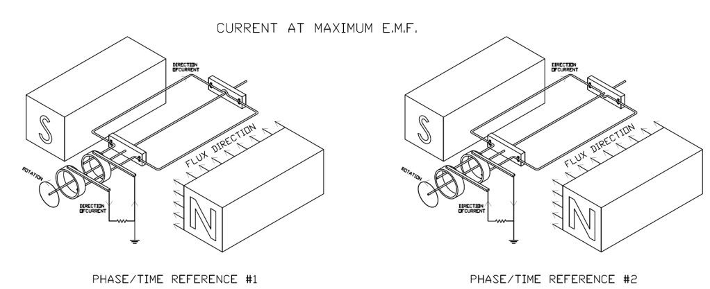
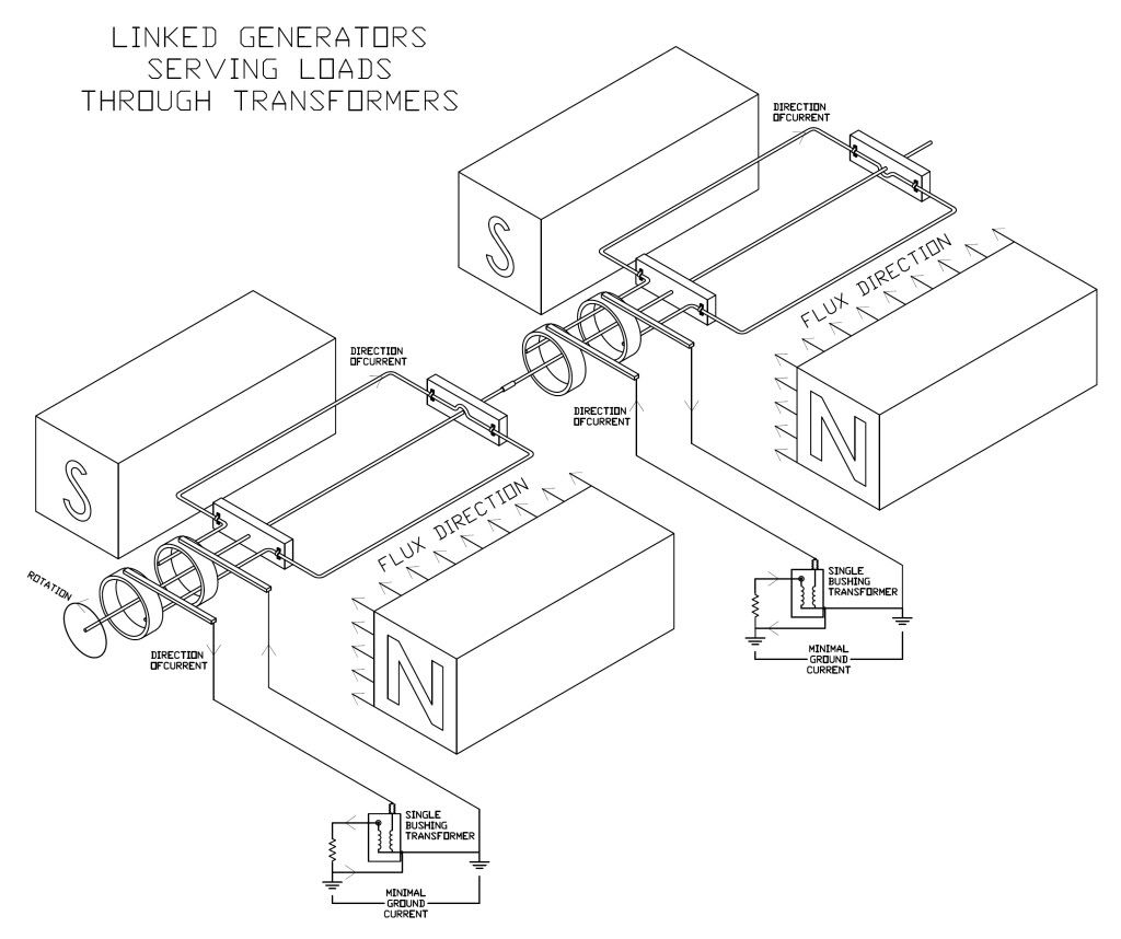
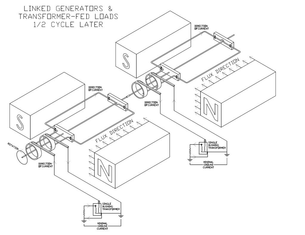
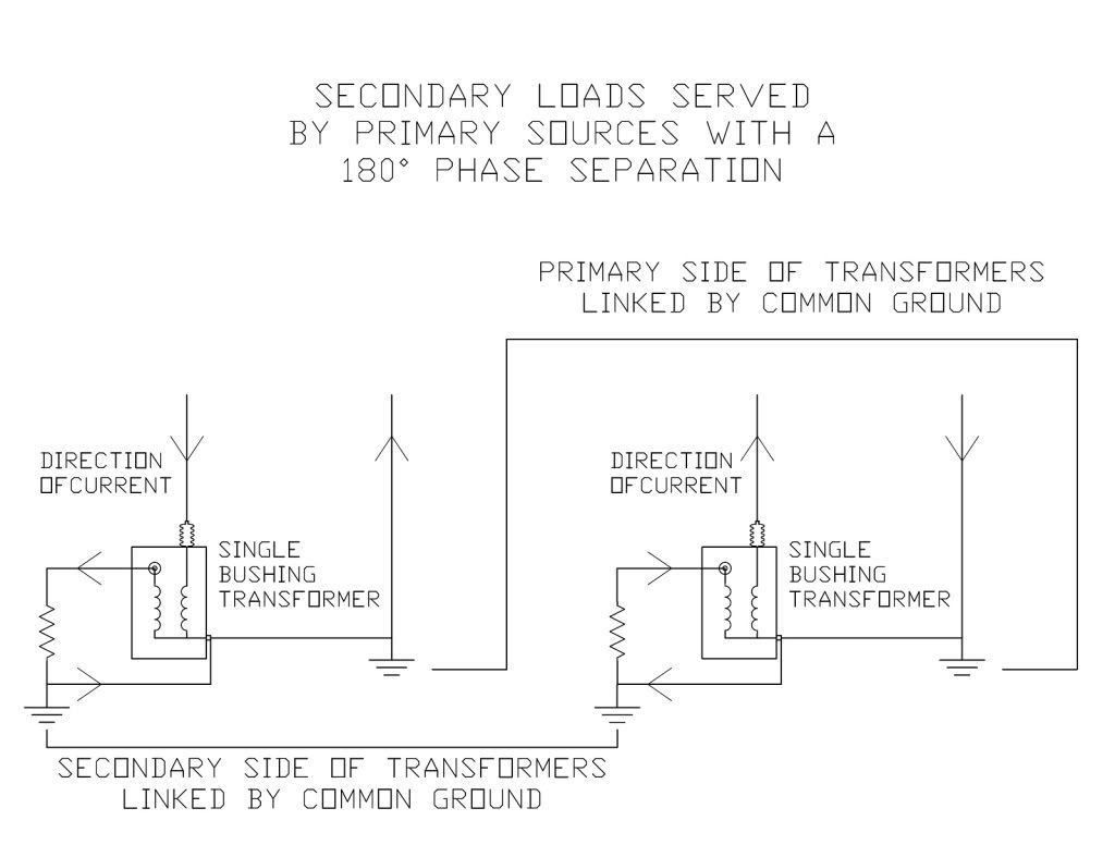
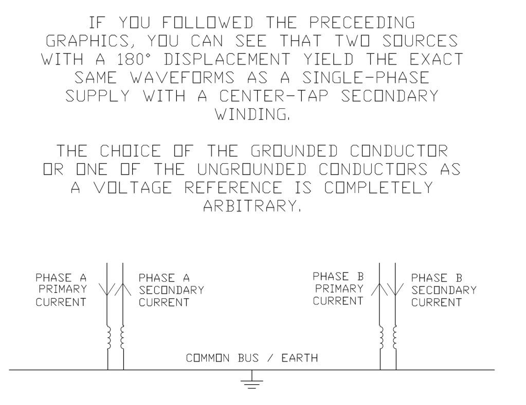
I hate to say it but in the real world Rick is correct, we have been accustom to using the phrase 180? for a long time to explain such things as canceling out fields in conduit and transformers in how the work, but in reality the voltage supplying a "single phase load" comes from only one single source that only has a + terminal and a - terminal it is a single pole in a generator that gives us this source and is no different then if it was a single battery being rotated 60/50 times a second it has the same + and - this pole in the generator has, the reason Rick is stating that one end of the transformer or the center tap is never out of phase is it's not, take a point in time when X1 is full positive and X2 will always be at full negative, this reference in time will never change,and when X1 is full negative X2 will be full positive this relation between X1 and X2 will always stay the same, now in a Polly phase system you have introduce an offset in the time when the second pole X1 reaches full positive and its X2 reaches its full negative again the reference between X1 and X2 of pole 2 will alway happen at the same time on the rotation of the 360? of the armature, but now you have inserted a vector delay between pole one and pole two it can be 120? or 90? depending upon the system, but it now has rotation and a phase angle, this rotating angle cannot be created by a transformer alone.
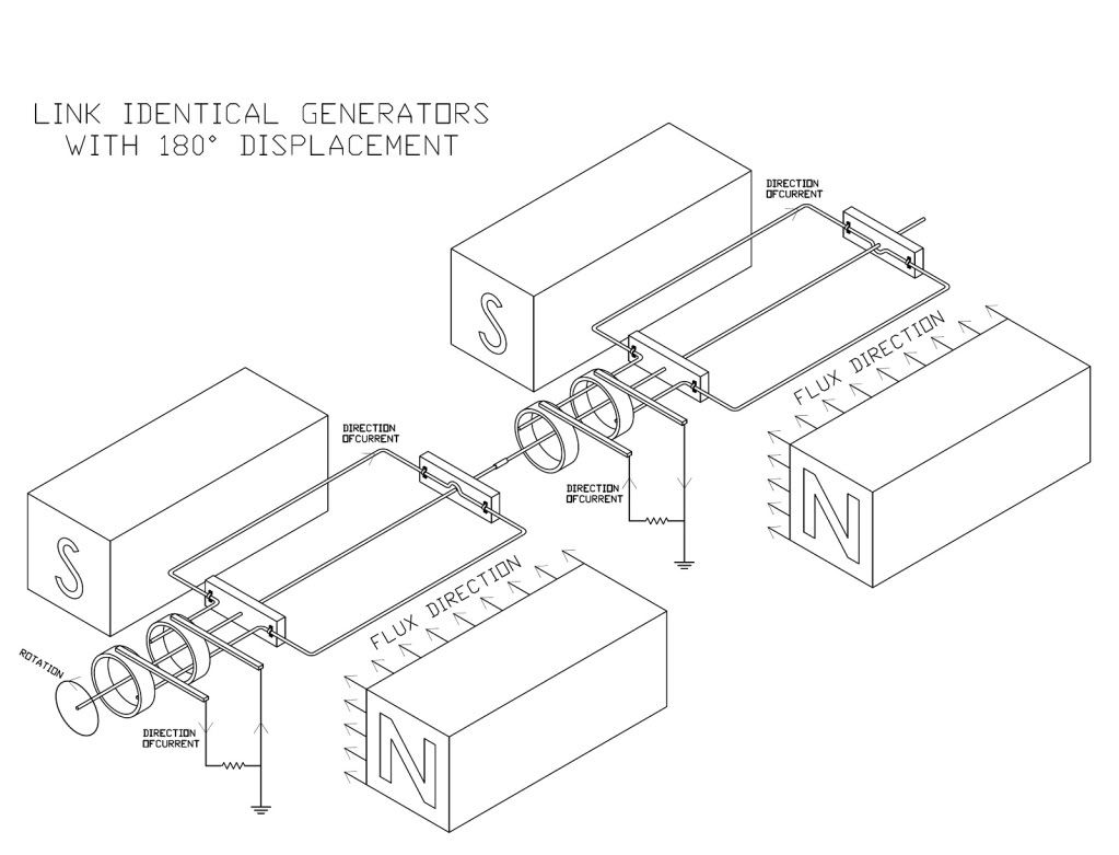
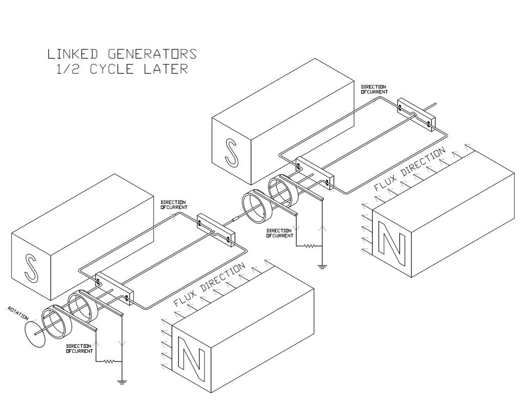
I tried to point this out in the thread awhile back when we we discussing the terminology of single phase and why it was not called two phase, I tried to point out that if you think of the source at any time you are connected to just two conductors of a 3 phase system you are only connected to one pole of the generator, take a three pole generator (simplified) each pole will have two conductors coming out of the pole, with 3 poles 120? apart you will have 6 leads connect them together to form a delta, now draw three lines one from each of the connection point if you connect to only two of those conductors you will only have one pole of that generator connected to the load, you will have a positive voltage on one and a negative voltage on the other that will swap 60 times in one second but in perfect sync not out of phase.
Saying one conductor is 180? out of phase with the other would have the same meaning of saying that one end of a battery is 180? out of phase with the other just because one is positive and the other is negative.
I know I'm a little rusty in the way of explaining this, but hammer away
Last edited: