- Location
- Connecticut
- Occupation
- Engineer
Show the simple math on the 240V system Mivey. You can't solve the equations without using double negatives for your choice of reference.
Vload+Vbn-Van=0. Where is the double negative?
Show the simple math on the 240V system Mivey. You can't solve the equations without using double negatives for your choice of reference.
I was on top of an "A" frame ladder about 16 feet above the concrete floor when I fell.
Vload+Vbn-Van=0. Where is the double negative?
Have you solved all of my loop questions?
Take two unequal size resistors, connect them in series, power them from a 240V 2-Wire source.
Does the loop current have the same phase angle as the voltages across each resistor?
Do the voltages across the resistors have the same phase angle as the source voltage?
Is the loop current in phase with the source voltage?
Take the exact same resistors in series, except power them from a 240V 2-Wire source created from (2) 120V supplies connected in series.
Does the loop current have the same phase angle as the voltages across each resistor?
Do the voltages across the resistors have the same phase angle as the (2) supply voltages?
Is the loop current in phase with each of the supply voltages?
If we can't agree on the answers to this simple connection of loads and sources, it will be impossible to agree on the answers to anything.
Vload+Vbn-Van=0. Where is the double negative?
Vl1+Vl2+Vba=0
Vl1+Vl2+Vbn-Van=0. What's the issue?
First determine your load direction. Presumably from your equation Vload = Vab
Vab = Vnb + Van = - Vbn + Van :: Vab + Vbn - Van = 0
240<0 = 120<0 + 120< 0 = - ( -120<0 ) + 120<0 :: 240<0 + ( -120<0 ) - ( 120<0 ) = 0
So since you asked nicely, there ya go. A double negative.
Do the voltages across the resistors have the same phase angle as the (2) supply voltages? - I believe your answer is NO, based on your choice of supply reference point.
Does the loop current have the same phase angle as the voltages across each resistor? - I believe your answer is YES, based on your formula Vl1+Vl2.
Is the loop current in phase with each of the supply voltages? I believe your answer is NO, based on your formula Van-Vbn.
Again, yes the loop current is in phase with each of the supply voltages. The loop current defined as "leaving" from terminal A is 8<0. That same loop current would be seen as "entering" terminal B. When referenced as "leaving" terminal B, the loop current is -8<0, or 8<180. So the loop current referenced from Supply Voltage A (120<0V) is 8<0A. The loop current referenced from Supply Voltage B (120<180V) is 8<180A.
You chose the loop current as "8<0" so it appears you have chosen Supply Voltage A as your reference for solving this loop. So now you have a 100% resistive current at 0? 'driven by' a source at 180?.
So the loop current referenced from Supply Voltage A (120<0V) is 8<0A.
Back to the basics: To be a series circuit, the currents will be the same in all parts of the circuit. Without the neutral, this is the case. With the neutral in the circuit, the currents in the sources can be, and almost always are, different.Are you saying that a center tapped transformer is not two sources in series?
It is a simple fact that a two wire source has only one voltage but the three wire source has two voltages (three if we include the larger voltage). They are simply not the same. Anyone who has lost a neutral can tell you that.When have I said you must do something?
I have stated that the presence or absence of a load neutral should not require a change in the way the sources are viewed.
And how do you suppose that losing a neutral is the same circuit that you had before? We have gone from a source with two smaller single-phase voltages and one larger single-phase voltage to a source with just one single-phase voltage. Hardly the same at all.I have asked you to solve a simple loop that would be typical of a 120/240V center tapped transformer that looses the load neutral connection.
I think it should be explicitly mentioned what you use as a reference whether or not that reference is the neutral point.Oh yeah, I have suggested that it should be explicitly mentioned that the neutral point is your reference when you say 120<0 and 120<180 combine to be a 120/240V source.
But you said that one of the source voltages(Vbn) is at 180?, so for the purposes of solving this loop you have a resistive current out of phase with a source voltage.No, the loop current at 0? is driven by a source at 0?
Since energy can neither be created or destroyed, it was definitely converted to some other form of energy.No, the potential was converted to kinetic and then to deformation. The potential is gone.
Who knows? The Earth might have started spinning just a tad faster.Since due to inertia and friction the Earth did not move at all, his testimony is correct. To move the Earth he wouldn't be he.
If two balls of equal mass were positioned in deep, empty outer space within appreciable ranges of their space distortion, the gravitational forces will pull them together. Now who is to say which one moved in which direction? You have to define a reference frame and there is no "right" or "wrong" reference frame.Yes there is a defined direction for r. It's an absolute distance and therefore never negative.
Looking ahead, I see David already answered that.Show the simple math on the 240V system Mivey. You can't solve the equations without using double negatives for your choice of reference.
Electricity 101. I still find it incredible that so many are still struggling with it. The only thing that comes to mind is that they are trying to change fundamental electrical theory to fit a model that they have become accustomed to over the years. I can understand someone getting in a rut, but that excuse will only stretch so far.So the loop current referenced from Supply Voltage A (120<0V) is 8<0A. The loop current referenced from Supply Voltage B (120<180V) is 8<180A.
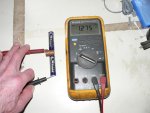
Since when does a constant, direct current have a phase?So, when I move the black lead to the top of the stack and the voltage display goes negative, do you want to say "it's 180 out of phase".
Do you really understand flux or are you just throwing that out there because it "sounds" good? How do you propose that it is going to dictate the voltage direction? I'm open to studying any theory you might be proposing but I suspect you are mis-interpreting some of the known theory. Feel free to post the theory that shows the voltage directions must be the same as I do not recall the one you might be referencing.From the transformer looking out, the magnetic flux direction the the winding turn direction always match exactly, the same.
FYI: Polarity and voltage direction are not the same thing.From the load looking at it's source, you have two sources and a range of connection choices, series, parallel, and polarity reversal - having the windings in series either add or subtract voltages.
I apologize for that. It sounds snippish and mean.Do you really understand flux or are you just throwing that out there because it "sounds" good?.