You are using an out of date browser. It may not display this or other websites correctly.
You should upgrade or use an alternative browser.
You should upgrade or use an alternative browser.
240v debate....
- Thread starter stickboy1375
- Start date

- Status
- Not open for further replies.
- Location
- Wisconsin
- Occupation
- PE (Retired) - Power Systems
But in the end, it does not matter so much how we choose to describe them. For example, I can say two sine waves are 180 degrees out of phase with each other, or I can say they occur simultaneously and reach their oppositely-signed peaks at the same moment, and it does not matter which of these I choose to say. So long as we take care in the choice of reference points, choice of positive and negative signs for voltage measurements, choice of positive and negative directions of current flows, and other related choices, then two seemingly different descriptions can both be accurate descriptions.
My point is not how they are described, it is how they relate to the physics of the real world.
Faraday's Law of Induction, basically says a magnetic flux creates a voltage. The 'Right Hand' rule is often used to explain the relationship between a magnetic flux and the current it generates. Fleming's Rules (right and left hand) describe the relationship between a voltage (emf), the direction of the flux, and the motion of the conductor versus the field. They relate specific directions to the voltage, flux and current involved in a single core, single winding transformer.
- Location
- Lockport, IL
- Occupation
- Retired Electrical Engineer
EEEEE-ther, EYE-ther, KNEE-ther, NIGH-ther! What say we call the whole thing off? :happyyes:
- Location
- Wisconsin
- Occupation
- PE (Retired) - Power Systems
EEEEE-ther, EYE-ther, KNEE-ther, NIGH-ther! What say we call the whole thing off? :happyyes:
That is more like Van+Vnb=Van-Vbn=Van-(-Vnb)=-(-Van+Vbn) ad infinitum
By the way, which part of this long discussion has said this application of math principals is wrong?
I have been asking how a single magnetic flux can yield multiple voltage directions in a single winding on a single transformer core.
Which "rule" would I use to model this?
Maybe it actually is time to post this question in a new thread?
Last edited:
That's tomorrow.Haven't you been eaten by a Morlock by now?
Seconded.Gentlemen, math only. I may be a low level grunt, but I want numbers-not words.
Yes, you may tell me to take a hike.
I can't see your diagrams for some reasonIn post #433, you claimed
"that your circuit, as drawn, is wrong."
Please post what YOU think is a correct version.
Without dancing around the topic.
Engineering Calculations as a new thread.That is more like Van+Vnb=Van-Vbn=Van-(-Vnb)=-(-Van+Vbn) ad infinitum
By the way, which part of this long discussion has said this application of math principals is wrong?
I have been asking how a single magnetic flux can yield multiple voltage directions in a single winding on a single transformer core.
Which "rule" would I use to model this?
Maybe it actually is time to post this question in a new thread?
mivey
Senior Member
Polarity only tells you what direction they flow relative to flow in other parts of the circuit at a specific point in time. Polarity does not tell you in what direction you must use the voltage force.But does not the polarity control the direction? Choose which flow you want, electron or conventional, does the polarity not control the direction in which the electrons flow?
mivey
Senior Member
Since current flows from a higher to lower potential, we can use the standard convention that the positive terminal of a source is the one out of which current flows to a load and the negative terminal is the one into which current flows from the load. Now consider Besoeker's pulse circuit with terminals a, n, and b where a is the top terminal, n is the center-tap terminal, and b is the bottom terminal.But does not the polarity control the direction?
When a has a higher potential than n, the current flows out to the load from a and from the load into terminal n. When a has a lower potential than n, the current does not flow in that half of the winding.
When b has a higher potential than n, the current flows out to the load from b and from the load into terminal n. When b has a lower potential than n, the current does not flow in that half of the winding.
Thus, we label the terminals a & b the positive terminals and n the negative terminal. The voltages rises from negative terminal to positive terminals are out of phase by 180 degrees.
What's so hard about that?
- Location
- Wisconsin
- Occupation
- PE (Retired) - Power Systems
This only works when there is a neutral conductor. If there is no neutral conductor are you saying current only flows in half of a single winding center tapped transformer? How do you explain the current flow in 2-wire circuit fed from a 3 terminal transformer?When a has a higher potential than n, the current flows out to the load from a and from the load into terminal n. When a has a lower potential than n, the current does not flow in that half of the winding.
When b has a higher potential than n, the current flows out to the load from b and from the load into terminal n. When b has a lower potential than n, the current does not flow in that half of the winding.
hurk27
Senior Member
- Location
- Portage, Indiana NEC: 2008
This site here explains it fairly well:
http://www.allaboutcircuits.com/vol_2/chpt_10/1.html
About half way to the bottom.
http://www.allaboutcircuits.com/vol_2/chpt_10/1.html
About half way to the bottom.
Nobody is suggesting that anything extraordinary is going on with the flux. The simple fact (yes, fact) is that, for the single phase centre-tapped transformer, Van and Vbn are mutually displaced by 180deg.I have been asking how a single magnetic flux can yield multiple voltage directions in a single winding on a single transformer core.
See post #333.
Flemming's left and right rules generally relate to (DC) motors and generators respectively hence the thumb for motion. One wouldn't ordinarily expect much motion within a transformer under normal operating conditions.My point is not how they are described, it is how they relate to the physics of the real world.
Faraday's Law of Induction, basically says a magnetic flux creates a voltage. The 'Right Hand' rule is often used to explain the relationship between a magnetic flux and the current it generates. Fleming's Rules (right and left hand) describe the relationship between a voltage (emf), the direction of the flux, and the motion of the conductor versus the field. They relate specific directions to the voltage, flux and current involved in a single core, single winding transformer.
jwelectric
Senior Member
- Location
- North Carolina
Since current flows from a higher to lower potential, we can use the standard convention that the positive terminal of a source is the one out of which current flows to a load and the negative terminal is the one into which current flows from the load. Now consider Besoeker's pulse circuit with terminals a, n, and b where a is the top terminal, n is the center-tap terminal, and b is the bottom terminal.
When a has a higher potential than n, the current flows out to the load from a and from the load into terminal n. When a has a lower potential than n, the current does not flow in that half of the winding.
When b has a higher potential than n, the current flows out to the load from b and from the load into terminal n. When b has a lower potential than n, the current does not flow in that half of the winding.
Thus, we label the terminals a & b the positive terminals and n the negative terminal. The voltages rises from negative terminal to positive terminals are out of phase by 180 degrees.
What's so hard about that?
So what you are saying is that an AC transformer that has a center tap will only have direct current flowing in one half of the transformer at one time and will never alternate.
jwelectric
Senior Member
- Location
- North Carolina
Does this mean what you said in the post above where there is current flowing from A to neutral point and from B to neutral point at all times but never current flowing from A to neutral point at the same 1/120th second that current is flowing from B to neutral point?Nobody is suggesting that anything extraordinary is going on with the flux. The simple fact (yes, fact) is that, for the single phase centre-tapped transformer, Van and Vbn are mutually displaced by 180deg.
See post #333.
I think I?m beginning to understand this so please don?t stop explaining
mivey
Senior Member
There is no point in making silly statements like this. You and I both know that is not true.This only works when there is a neutral conductor. If there is no neutral conductor are you saying current only flows in half of a single winding center tapped transformer?
It is a series circuit. A two-terminal circuit (the 3rd terminal does not enter the picture for the two-wire circuit) is not the same as a three-terminal circuit.How do you explain the current flow in 2-wire circuit fed from a 3 terminal transformer?
mivey
Senior Member
And if you can see that, I'll say you & I are in agreement up to this point like I think Rick & I are in agreement up to this point. Jim should be, but I really do not know if he can agree that you can have two 180? displaced sources without playing math games with the terminals.This site here explains it fairly well:
http://www.allaboutcircuits.com/vol_2/chpt_10/1.html
About half way to the bottom.
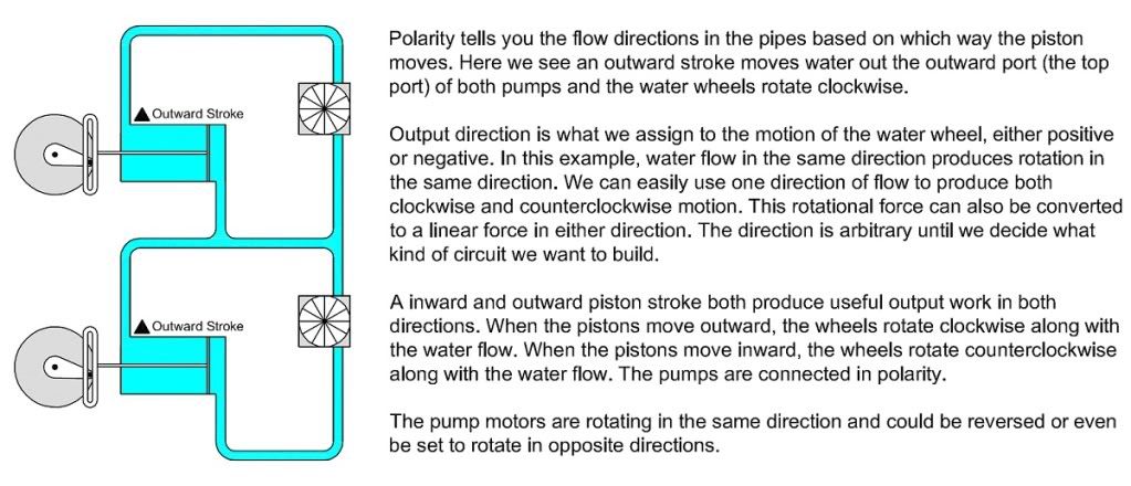
As for polarity vs. direction, I made some water flow graphics that may clarify for those who can follow water flow easier than electric theory. The first shows two pumps connected in polarity and the second shows two pumps connected in opposite polarity. You should be able to follow the graphics and see that while polarity and direction are related, they are not the same thing.
Same polarity:
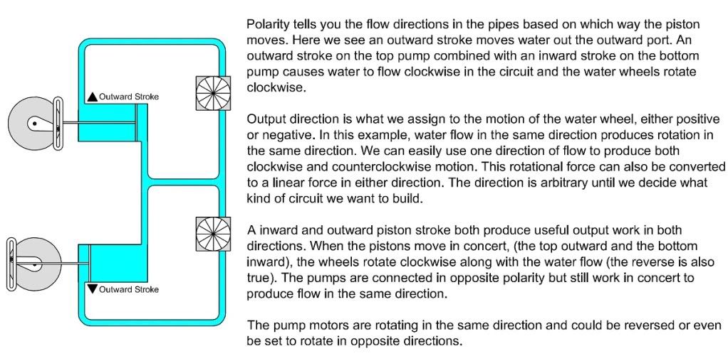
Opposite polarity:
mivey
Senior Member
I'm certainly not. The problem is that the others are trying to make the laws dealing with flux and voltage say something that they do not say.Nobody is suggesting that anything extraordinary is going on with the flux.
mivey
Senior Member
With the circuit that Besoeker has, the load current in the winding halves will only flow from the center to the ends of the windings and will never flow from the ends towards the center-tap. One half will flow in one direction and the other half will flow in the other direction.So what you are saying is that an AC transformer that has a center tap will only have direct current flowing in one half of the transformer at one time and will never alternate.
That is not the case without the diodes.
mivey
Senior Member
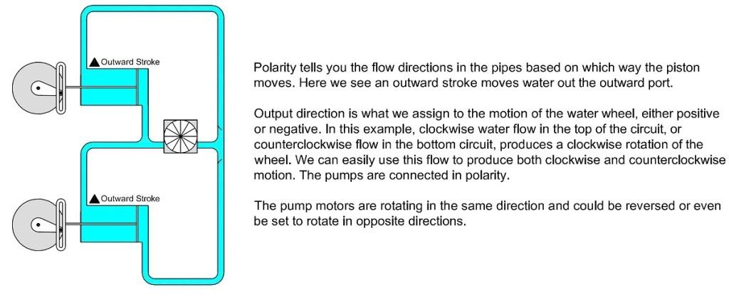
I made some water wheel graphics that illustrate Besoeker's circuit.Does this mean what you said in the post above where there is current flowing from A to neutral point and from B to neutral point at all times but never current flowing from A to neutral point at the same 1/120th second that current is flowing from B to neutral point?
I think I’m beginning to understand this so please don’t stop explaining
This is his circuit with the pumps in polarity. You will notice that the water in the top half only circulates clockwise and the water in the bottom half only circulates counterclockwise. That is because of the one-way flapper valves (diodes). It might be hard to see at this resolution but the flapper vales pivot on the left side and are open on the right side.
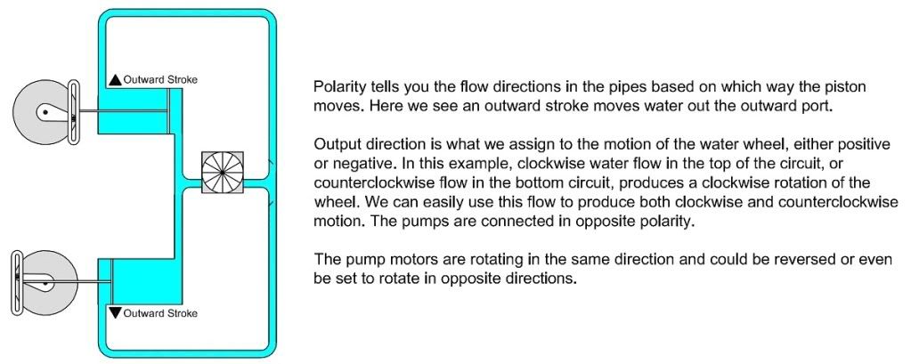
Here is the same circuit but using pumps connected in opposite polarity:
Last edited:
mivey
Senior Member
Please forgive my 1st sentence as it served no useful purpose. I should keep those comments to myself. Sorry.There is no point in making silly statements like this. You and I both know that is not true.
- Location
- Wisconsin
- Occupation
- PE (Retired) - Power Systems
You simply refuse to acknowledge the physics of a transformer, because it conflicts with your position that the circuit should be solved using the neutral point to define voltage direction.I'm certainly not. The problem is that the others are trying to make the laws dealing with flux and voltage say something that they do not say.
If the construction of a single core transformer is of no concern then why are there industry standards regarding the designation of the terminals? Why do we care about polarity dots when connecting transformers? ANSI standards say that when current is flowing into H1 a corresponding current is flowing out of X1 doesn't this then define a direction?
- Status
- Not open for further replies.