7200 volt to 120/240 volt single phase transformer

Status
Not open for further replies.

jim dungar

Moderator
Staff member
Location
Wisconsin
Occupation
PE (Retired) - Power Systems
Yes. If you want to see how the two 120 voltages Van and Vbn are related in time wrt a common point the N centre tap is the only choice for that common point. Any other won't give you two 120s. Two hots, one neutral.

You bolded the word must. I highlighted your use of the verb see.
What if i don't want to use a neutral. What if I want to use an isolated dual channel scope and view the two voltages Van and Vnb? Would this not show a time relation between them?


It is perfectly accurate to say 1/2 - (-1/2) = 1, but I don't think you would do this to explain how two halves make a whole.
 

jwelectric

Senior Member
Location
North Carolina
What I will see on the scope is two voltages that are displaced by 180 degrees but this is simply because of the way the scope is connected.
Yes. If you want to see how the two 120 voltages Van and Vbn are related in time wrt a common point the N centre tap is the only choice for that common point. Any other won't give you two 120s. Two hots, one neutral.
But this does not mean that the voltages are 180 degrees out of each other it only means that this is the way I have connected the scope.


I can see no way that a single core transformer can displace the magnetic flux of the secondary in two different directions that are separated by 180 degrees.
I don't imagine that anyone with even the most basic knowledge of transformer theory would argue otherwise. See post #7

So does this mean that you agree that the two lines are of the same accord or in phase with each other and not 180 degrees out?
 

mivey

Senior Member
No I am not just looking to argue just trying to reach a consensus as to the 120 volt sine wave.
OK. My apologies. It just sounded like it.

Are they or are they not in sync with each other. Do they or do they not oppose each other.
The forces are not in opposition. They work together or we would not get 240 volts. Again, the direction we take the positive force is the difference. The force in the transformer is changing direction every 1/2 cycle. We can take a positive voltage force in either direction.

In order to address this issue with your drawing of the batteries the center tap of the transformer would have to relate to the midpoint between the two 1.5 volt batteries.
It does

What you are showing is the full sine wave of 240 (3) volts as it goes through one full cycle.
It shows both the 120 (1.5) and the 240 (3).

Now address the 120 volt and the center tap. If as you say the two 120 volt sine waves are 180 degrees out of phase with each other then one of the 1.5 volt batteries will need to be turned 180 degrees.
No. Then the forces would be in opposition.

I have one secondary power source of 240 volts that has a center tap. Your batteries have a power source of 3 volts with a center tap. If as you say the two 120 volts are 180 degrees out of phase with each other then make the two 1.5 batteries be 180 degrees out of line with each other.
The direction of we take positive voltages can be different. The transformer is producing a force in opposite directions every 180?.

If it won?t work with DC then it won?t work with AC either.
The issue is that DC does not really cycle and there is no phase difference with DC. DC only has one positive direction we can use. AC has two positive directions we can use.

I can see no way that a single core transformer can displace the magnetic flux of the secondary in two different directions that are separated by 180 degrees.
That is not what is happening


As with the two 1.5 batteries should they oppose each other by 180 degrees they would simply cancel each other out and there would be no voltage reading across the total bank at all. Is this not simple vector addition?
Maybe we should just go back to the AC examples as the DC is not helping you.

You bolded the word must. I highlighted your use of the verb see.
What if i don't want to use a neutral. What if I want to use an isolated dual channel scope and view the two voltages Van and Vnb? Would this not show a time relation between them?
Magnitude for sure. Time also, depending on your trigger.

It is perfectly accurate to say 1/2 - (-1/2) = 1, but I don't think you would do this to explain how two halves make a whole.
If you had a DC device that needed a +/- 12v, +/-9v, and +-5v power source, would you say "Oh no! You guys have it all wrong because that kind of supply would break the laws of electricity! What we really need is a 3v, 7v, 12v, 17v, 21v, 24v power source."?

But this does not mean that the voltages are 180 degrees out of each other it only means that this is the way I have connected the scope.
No. The transformer really is producing forces in two different directions at a 180? displacement.
 

jwelectric

Senior Member
Location
North Carolina
Maybe we should just go back to the AC examples as the DC is not helping you. No. The transformer really is producing forces in two different directions at a 180? displacement.

The DC is exactly what is helping me to understand that the second half of the statement can't be true.
For a time period of 1/120 of a second which repeats its self should the two 120 volt forces be 180 degrees out of sync with each other it would be the same as taking two batteries and reversing one of them. Positive 120 volts plus negative 120 volts equals no voltages unless my math is wrong.
 
T

T.M.Haja Sahib

Guest
Does the secondary of a 120/240 volt single phase transformer have two 120 volt phases that are 180 degrees out of phase with each other?
If the secondary winding has the same direction clockwise or counterclockwise around the core both for the two 120V phases,the voltages induced in them are in phase.Otherwise they are 180 degrees out of phase with each other.
 

mivey

Senior Member
Mike,

See if these graphics help clarify what myself & others have been saying:

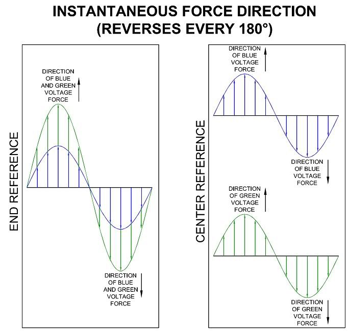
The first graphic shows the instantaneous forces in a transformer. For our discussion, let polarity marks (not shown) indicate the up direction as positive.

For half of the time the forces are in one direction, and for the other half the forces are in the opposite direction. The left side of the graphic shows the force from one end of the winding and how they sum across the winding to double the force. As you can see, the direction of force only agrees with the polarity mark half the time. As I have said, direction and polarity are not the same thing.

The right side shows the voltages taken from the center (required two graphs because the waves lay on top of each other). If you take them in the same direction, you get the same composite as the first graph.

SinusoidalInst.jpg


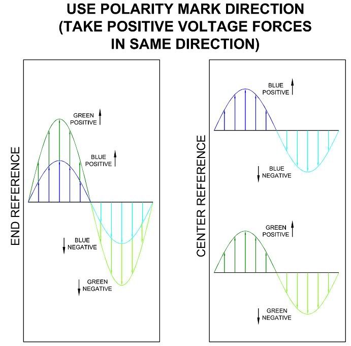
The next graphic shows what happens when we take the positive forces all in the same direction using the polarity marks. This gives us "positive forces" and "negative forces" (i.e., positive and negative voltages).

No matter what direction we take to be positive or negative, the forces in the same direction still give us double the force. In this case, we are saying the positives are 180? displaced from the negatives. As you can see, the direction we call positive always matches the polarity marks.

We take both positive voltages at the same wave point, so the voltages are "in-phase". They only match the force direction half the time.


SinusoidalPolarity.jpg


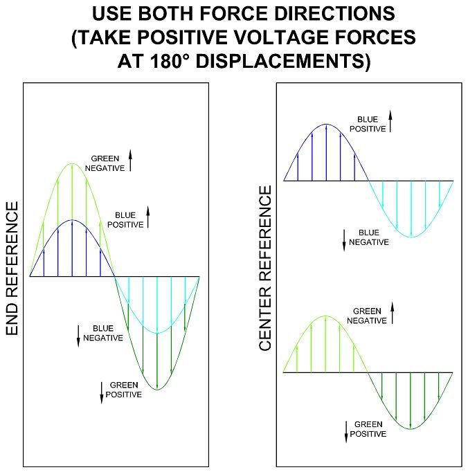
This final graphic shows what happens when we take the "positive force" of half of the winding to be in one direction and the "positive force" of the other winding to be in the opposite direction (one with polarity, one against polarity). This gives us "positive forces" and "negative forces".

No matter what direction we take to be positive or negative (even though we take it differently for each winding half), the forces in the same direction still give us double the force.

In this case, we take one positive voltage 180? displaced from the other positive voltage so they are "phase-opposed". As you can see, the direction we call positive for one wave always matches the polarity mark. The direction we call negative for the other wave always matches the polarity mark.

Sinusoidal180.jpg


No matter how we take the voltages from the transformer, or which direction (or directions) we call positive, the forces inside the transformer do the same as they would do otherwise.

We see that we can take either direction to be a positive direction because it is just a matter of timing. There is no universally "correct" direction.

We can produce these exact same forces with two generators in phase. Then we might claim there is only one correct direction.

We can produce these exact same forces with two phase-opposed generators. Then we might claim both directions are correct.

We can produce these exact same forces with two generators in phase but phase-opposed to other generators that are in phase. Then we might claim this new direction is the only one correct direction.

That is why the laws of electricity do not specify the "correct" direction for taking voltages because if they did, they would eventually produce a paradox. It just ain't going to happen and if anyone tries to make you believe the laws say you can only take voltages in one "correct" direction, they do not understand how things really work.

In truth, the direction is oscillating and our choice as to how we will take the voltages from the source is arbitrary. None of the directions we choose will contradict any electric law. If you think they do contradict the laws, you are trying to make the formulas or laws say something they do not say.
 
Last edited:

mivey

Senior Member
If the secondary winding has the same direction clockwise or counterclockwise around the core both for the two 120V phases,the voltages induced in them are in phase.Otherwise they are 180 degrees out of phase with each other.

There is nothing that dictates what direction we have to use as positive when we take the voltages. The forces in the transformer will be the same whether we used two generators that had voltages out of phase or whether we used two generators with voltages in phase.

See my posts #98 here and #290 here
 

mivey

Senior Member
The DC is exactly what is helping me to understand that the second half of the statement can't be true.
For a time period of 1/120 of a second which repeats its self should the two 120 volt forces be 180 degrees out of sync with each other it would be the same as taking two batteries and reversing one of them. Positive 120 volts plus negative 120 volts equals no voltages unless my math is wrong.
The problem is that you can't reverse just one battery. That is like trying to get two different force directions in the winding.

See my graphics with the waveforms and see if that answers your questions.
 

Besoeker

Senior Member
Location
UK
You bolded the word must. I highlighted your use of the verb see.
What if i don't want to use a neutral. What if I want to use an isolated dual channel scope and view the two voltages Van and Vnb? Would this not show a time relation between them?
It would, of course, Vnb being the anti-phase of Vbn. But you would be displaying the two 120V outputs in a way that doesn't reflect how the transformer is connected or operates. It doesn't have two isolated 120V outputs.
 

jwelectric

Senior Member
Location
North Carolina
The problem is that you can't reverse just one battery. That is like trying to get two different force directions in the winding.

See my graphics with the waveforms and see if that answers your questions.

This is exactly what I am trying to say. If I reverse one of the batteries then I would have two forces that were pushing against each other. If the two 120 volt halves of the secondary was 180 degrees out or one was turned around then the two forces would be pushing against each other.

Should I connect a scope to one of the two cell battery banks that you posted where the batteries are in series with each other using the two ends as A and B and the midpoint of the two as common would not the scope show two 1.5 volts that are 180 degrees apart?

Two of my brothers and I rented a room one night while traveling across country. We each paid $10 for the room making the total $30. Next morning the owner got to thinking this was too much for that room so he gave his little boy 5 one dollar bills and told him to divide the money between the three of us. The little boy couldn?t divide the money equally so he decided that he would give us $1 back and keep $2 for himself. This leaves us paying $9 apiece for the room which totals $27 and the little boy kept $2 which totals $29

The moral of that story is; if we just try to keep it simple and stupid it is really easy to understand. When we start complicating it with a bunch of explanation and trying to prove it with math it really gets confusing.
 

mivey

Senior Member
This is exactly what I am trying to say. If I reverse one of the batteries then I would have two forces that were pushing against each other. If the two 120 volt halves of the secondary was 180 degrees out or one was turned around then the two forces would be pushing against each other.

Should I connect a scope to one of the two cell battery banks that you posted where the batteries are in series with each other using the two ends as A and B and the midpoint of the two as common would not the scope show two 1.5 volts that are 180 degrees apart?
It would show one positive relative to the reference and one negative relative to the reference . The catch with DC (picking the a-n-b direction as positive for a beginning) is that b will ALWAYS have a higher potential than n and n will ALWAYS have higher potential than a. With AC, that relationship is true only half the time and that alteration is what allows us to have two positive voltages taken in opposite directions with a 180? phase difference.

Two of my brothers and I rented a room one night while traveling across country. We each paid $10 for the room making the total $30. Next morning the owner got to thinking this was too much for that room so he gave his little boy 5 one dollar bills and told him to divide the money between the three of us. The little boy couldn?t divide the money equally so he decided that he would give us $1 back and keep $2 for himself. This leaves us paying $9 apiece for the room which totals $27 and the little boy kept $2 which totals $29

The moral of that story is; if we just try to keep it simple and stupid it is really easy to understand. When we start complicating it with a bunch of explanation and trying to prove it with math it really gets confusing.
I thought the moral of the story was that the boy couldn't be in two places at once (he has to stay on his side of the equal sign).
 

mivey

Senior Member
It would, of course, Vnb being the anti-phase of Vbn. But you would be displaying the two 120V outputs in a way that doesn't reflect how the transformer is connected or operates. It doesn't have two isolated 120V outputs.
We could parallel them but they still would not be isolated (we actually do that for some transformer banking). But without some common link between the voltages, there would be no fixed relationship.

It is funny how they want to fuss because we want to move the red lead to measure from a common connection, but they see nothing wrong with moving both the red and black leads to measure the series connection.

If the phase difference were not so, the open-wye to 4-wire wye would not work. Neither would your circuit with both voltages taken as positive relative to the neutral.

I still don't get why this is so hard for the others to see and I have about run out of different ways to demonstrate it.
 
T

T.M.Haja Sahib

Guest
There is nothing that dictates what direction we have to use as positive when we take the voltages. The forces in the transformer will be the same whether we used two generators that had voltages out of phase or whether we used two generators with voltages in phase.

See my posts #98 here and #290 here

Here we are talking about the phase relationship in the voltages induced in two windings on a common transformer core.The phase relationship between the two induced voltages depends on the direction each winding is wound around the core.Do you agree?
 

jwelectric

Senior Member
Location
North Carolina
It would show one positive relative to the reference and one negative relative to the reference .

.
The batteries are in series with one end of the bank ? and the other end of the bank + and they are both carrying current in the same direction although the scope shows them being 180 degrees out.

The same is true in the transformer.
 

mivey

Senior Member
Here we are talking about the phase relationship in the voltages induced in two windings on a common transformer core.The phase relationship between the two induced voltages depends on the direction each winding is wound around the core.Do you agree?
The direction of forces produced at a given instant speaks to the polarity relationship. The orientation of the primary and secondary windings and the direction of increasing & decreasing flux as the flux is cut by the secondary conductor (or more correctly as the flux pushes through the secondary winding conductor) determines at that instant what direction is increasing in potential and what direction is decreasing in potential. That is determined using the right hand rule (and saying that the flux pushing through the secondary is the same as the conductor cutting the flux in the opposite direction). The direction determined at that instant will be exactly opposite 180? later.

All of that is not the same as saying we must take a positive voltage across one half of the winding in the same direction we take a positive voltage across the other half of the winding, and that if we don't we do not get real voltages. The truth is that we can take positive voltages in either direction and if you don't believe it, just wait about 8.33ms and I'll prove it to you.

Given that the terminals in one direction across the winding are a-n-b, do you not agree that Van and Vbn have a 180? phase difference?
 

mivey

Senior Member
.
The batteries are in series with one end of the bank – and the other end of the bank + and they are both carrying current in the same direction although the scope shows them being 180 degrees out.

The same is true in the transformer.
No. Batteries do not change direction (alternate) like an AC signal does, as Laszlo pointed out earlier.
 
Last edited:
T

T.M.Haja Sahib

Guest
The direction of forces produced at a given instant speaks to the polarity relationship. The orientation of the primary and secondary windings and the direction of increasing & decreasing flux as the flux is cut by the secondary conductor (or more correctly as the flux pushes through the secondary winding conductor) determines at that instant what direction is increasing in potential and what direction is decreasing in potential. That is determined using the right hand rule (and saying that the flux pushing through the secondary is the same as the conductor cutting the flux in the opposite direction). The direction determined at that instant will be exactly opposite 180? later.

All of that is not the same as saying we must take a positive voltage across one half of the winding in the same direction we take a positive voltage across the other half of the winding, and that if we don't we do not get real voltages. The truth is that we can take positive voltages in either direction and if you don't believe it, just wait about 8.33ms and I'll prove it to you.

Given that the terminals in one direction across the winding are a-n-b, do you not agree that Van and Vbn have a 180? phase difference?

They will have a 180? phase difference,if one secondary winding is wound around the core in clockwise direction and the other in the anti-clockwise direction.But then unfortunately,there will be no 240 V volts,but only 120V across each secondary winding.It is because the two secondary windings are threaded by the same varying flux through the transformer core,the phase relationship between the two induced voltages are determined by the way the two windings are wound around the transformer core.

By the way,I want you to refresh your memory on the topic of phase groups of transformers discussed in Electrical Engineering textbooks in respect of how phase of induced voltage change with change in winding direction and change in terminal designation.
 

jwelectric

Senior Member
Location
North Carolina
It would show one positive relative to the reference and one negative relative to the reference
.
The batteries are in series with one end of the bank ? and the other end of the bank + and they are both carrying current in the same direction although the scope shows them being 180 degrees out.

The same is true in the transformer.
No. Batteries do not change direction (alternate) like an AC signal does, as Laszlo pointed out earlier.

Which is it, yes or no? First you say it does show that it is showing 180 and then you say no.
The changing of direction has no influence on this discussion as you are saying that the two sine waves of a 120/240 single phase transformer are 180 degrees out of phase for 1/120 of a second which means they would be opposing each other just as the reversed battery.

You even agree with this although you don?t openly admit to it. You even made this comment.
The right side shows the voltages taken from the center (required two graphs because the waves lay on top of each other). If you take them in the same direction, you get the same composite as the first graph.
Here you say that should you read the transformer in series the two sine waves would lap over each other and this is saying that the transformer is in phase with itself at all times.
 

Besoeker

Senior Member
Location
UK
Hello thought I would put my two cents in.

Every since I have been in the Electrical trade myself and other Electricians knew for a fact with
no doubt that in the Single Phase Electrical system feeding a house was just that single phase.

There is nothing out of Phase about it. It is only a polarity difference.Nothing is 180 degrees out.
Line one is line No. one and line two is line two and the center tap is a neutral between those two lines.

Interesting thing, that polarity difference....
Look at the following picture of the voltage waveforms:

120-0-120Vrev03.jpg


The show Van and Vbn being of equal magnitudes but different polarities for one complete cycle.
Do you see now that the polarity difference is the same as a 180deg displacement between the two waveforms?
The two are just different ways of describing the same thing.
 

mivey

Senior Member
They will have a 180? phase difference,if one secondary winding is wound around the core in clockwise direction and the other in the anti-clockwise direction.
That is completely wrong. Van and Vbn have a 180? difference and it is with the windings wound in the same direction.

By the way,I want you to refresh your memory on the topic of phase groups of transformers discussed in Electrical Engineering textbooks in respect of how phase of induced voltage change with change in winding direction and change in terminal designation.
Thanks, but I'm all up to date.

I would like for you to refresh your memory on what a voltage actually is. We are talking about voltage differences. The difference in voltage between two points is equal to the amount of work we to do to move a unit charge between those points against an electric field. How much work do think we have to do if the unit charge is moved in the same direction as the field? Where do you think the energy comes from?

Add: What direction would you assign if you work talking about work done by you vs work done by someone else?
 
Last edited:
Status
Not open for further replies.
Top