- Location
- Wisconsin
- Occupation
- PE (Retired) - Power Systems
Okay, now that we all agree that a single core single winding has a single flux which results in a single voltage 'direction'.
Please, bear with me on the usage of the concept of direction. Cutting the single winding into multiple sections, 50% and 20% are common points, does not change the direction of the 'created' voltages. Based on ANSI standard conventions this direction is in phase with the current.
Again allow me a little leeway, it is not uncommon to call the high potential terminal an odd number (i.e. X1), the low potential is an even number (i.e. X2), and indicate the direction of the voltage as an arrow pointing from low towards high (i.e. X4->X3).
So if I take two transformer coils, wound in the same direction on a common core, there will be a single voltage direction even though there are two voltages. Standard convention is to call them X1-X2 and X3-X4.
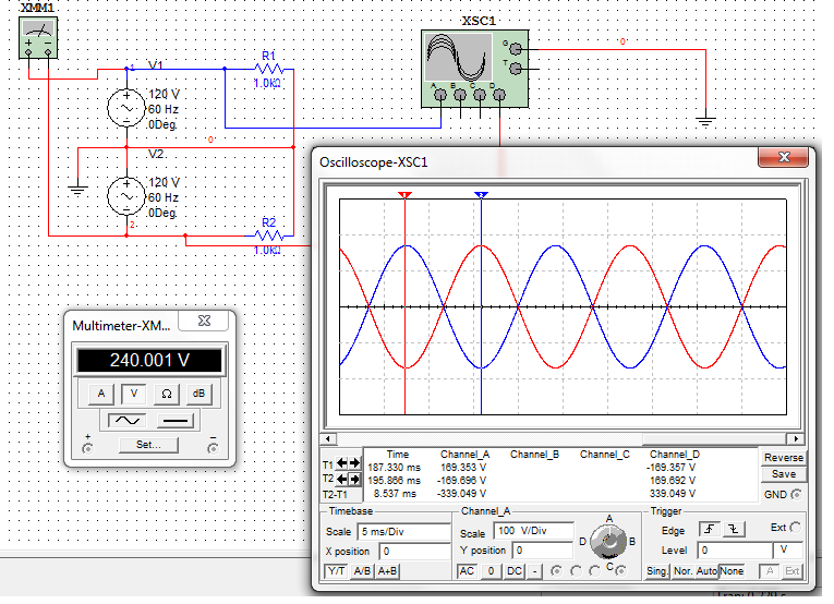
If I connect them in series one way would be X1-X2X3-X4 and my two voltage would add, because the direction of the voltages are 'in phase', we often indicate this by connecting the tail of one arrow to the point of the other (i.e. --->--->).
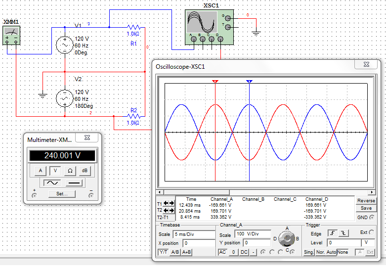
However if I connect them in series like X1-X2X4-X3, the two voltages would subtract because the direction of the voltages are 180? out of phase, which is indicated by connecting the tail of one arrow to the tail of the other (i.e. <------>).
Again, lets get agreement on this 'process' before we move on.
Please, bear with me on the usage of the concept of direction. Cutting the single winding into multiple sections, 50% and 20% are common points, does not change the direction of the 'created' voltages. Based on ANSI standard conventions this direction is in phase with the current.
Again allow me a little leeway, it is not uncommon to call the high potential terminal an odd number (i.e. X1), the low potential is an even number (i.e. X2), and indicate the direction of the voltage as an arrow pointing from low towards high (i.e. X4->X3).
So if I take two transformer coils, wound in the same direction on a common core, there will be a single voltage direction even though there are two voltages. Standard convention is to call them X1-X2 and X3-X4.
If I connect them in series one way would be X1-X2X3-X4 and my two voltage would add, because the direction of the voltages are 'in phase', we often indicate this by connecting the tail of one arrow to the point of the other (i.e. --->--->).
However if I connect them in series like X1-X2X4-X3, the two voltages would subtract because the direction of the voltages are 180? out of phase, which is indicated by connecting the tail of one arrow to the tail of the other (i.e. <------>).
Again, lets get agreement on this 'process' before we move on.