Why is residential wiring known as single phase?

Status
Not open for further replies.

Besoeker

Senior Member
Location
UK
The problem here is you showed both L1 and L2 as having 120V each at the same time........
There is no problem.
Look how the 0V ends of the windings are connected and the orientation of the windings in each of the two diagrams.
They are not the same. And intentionally drawn as they are precisely to illustrate the difference.

An ad from the internet.
XPWR054-120
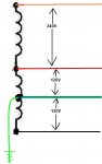
Power transformer for a 120V, 60Hz. line to 240V (120-0-120) at 100mA center tapped and 24V (12-0-12) at 2A center tapped.
This is how it gets described. Not 120, 0, -120.
 
Last edited:
T

T.M.Haja Sahib

Guest
There is no problem.
Look how the 0V ends of the windings are connected and the orientation of the windings in each of the two diagrams.
They are not the same. And intentionally drawn as they are precisely to illustrate the difference.

An ad from the internet.

This is how it gets described. Not 120, 0, -120.
If what you says is true,then L1 and L2 are at the same potential at any instant (for example 120v at the instant shown in your drawing) and so the two voltages L1-N and L2-N are in phase and so the two currents add in the neutral.
But you are showing a difference of the currents in the neutral in the drawing at post#119.Please speak your mind.Are you playing with us?
 

templdl

Senior Member
Location
Wisconsin
No, you can never derive 3ph from 1ph. But, you can combine 3ph to 1ph because I have sold them. As I am not a transformer engineer I am not sure of how the core and coils are engineer. They designed a transformer such that it shifted 2 of the phases to line up with the third. What I do remember is that the load on all three phases is not quite balanced as would be desire but is certainly more desirable than taking the 1ph load off of 1ph of a 3ph transformer.


The applications that I delt with was 3ph generators as a source where single phase was required.
I have the privilage of working with some very excellent seasoned as well as mature and exprerience transformer engineers and was amazed at some ofhe things hat they could do.

Yes, it would be logical that you could reverse a 3ph to 1ph transformer to be feed from a 1ph source but it can't be done because 1ph is 1ph. You can't generate a phase shilt from a 1ph source.
If you look closely at a 3ph transformer name plate it will show a wye and a delta symbol. It is how these symbols are aranged and marked that indicate the phase shift between primary and secondary of the transformer. The common transformer will be connected where the secondary lags 30deg which in the specifacation would be 'DY1" if it is specified in the writen specs. There are these combinations:
Group 1 : Zero phase displacement (Yy0, Dd0, Dz0)
Group 2 : 180o phase displacement (Yy6, Dd6, Dz6)
Group 3 : 30o lag phase displacement (Dy1, Yd1, Yz1)
Group 4 : 30o lead phase displacement ( Dy11, Yd11, Yz11)
With these phase shifts it provides a possibility it allows the transformer design engineer to design a transformer which shifts each phase to combine them as one ending up as one phase as well as to 2ph. Changing 2ph to 3ph is also possible. But with a 1ph source there is nothing to work with. I shipped a 3ph-2ph transformer to Mexico that must have been about a 1000kva and it was a strange looking thing with extra coils on top. It had to have need 7-8" tall.
The 3ph-1ph treanformers were supplied to private homeowners who had very large homes that were able to afford 3ph generators. One common application was for the new gas turbine gernerator which are only available in 3ph. These generators made it possible for them to cogenerat selling power back to the utilitys. I was pressed by the customer for then to be able to back feed the 3ph-1ph transformer in order to start the generator but I advised them that it wasn't possible.
 

Besoeker

Senior Member
Location
UK
If what you says is true,then L1 and L2 are at the same potential at any instant (for example 120v at the instant shown in your drawing)
The drawings aren't of a frozen instant in time and you are wrong to interpret them in that way. They are circuit arrangements.

This is the time relationship:

120-0-120Vrev03.jpg
 

Joethemechanic

Senior Member
Location
Hazleton Pa
Occupation
Electro-Mechanical Technician. Industrial machinery
So if this was the secondary of a transformer, how many phases would it be?
 

Attachments

  • howmanpha.JPG
    howmanpha.JPG
    26.8 KB · Views: 0
T

T.M.Haja Sahib

Guest
The drawings aren't of a frozen instant in time and you are wrong to interpret them in that way. They are circuit arrangements.

This is the time relationship:

120-0-120Vrev03.jpg
Your diagram itself speaks the truth:The voltage vector V1-N acts from V1 to N.The voltage vector N-V2 acts from N to V2.So the two voltages V1-N and N-V2 are in phase.But V1-N and V2-N are out of phase by 180 degree.But you are left with the Hobson's choice of voltages V1-N and N-V2 only.You can not make use of voltages V1-N and V2-N here.
 

Besoeker

Senior Member
Location
UK
T

T.M.Haja Sahib

Guest
Brilliant deduction. It's what I have been saying ad nauseum.


No, you're not.


Of course you can. Never heard it being informally referred to as two hots and one neutral?
See V1-N voltage vector 120v is directed from L1 to N.N is grounded and its voltage is 0v.N-V2 voltage vector is directed from N to L2.Its magnitude is -120v.These two vectors V1-N and N-V2 are in phase.One is 120v vector(V1-N) and another is -120v vector(N-V2).If N-V2 voltage vector is reversed,it becomes 120v vector(V2-N). So if the potential at L1 is 120V,the potential at V2 would also be 120v,both with respect to N.So the two currents from L1 and L2 add in it.But this does not actually happen here.Only the voltages V1-N and N-V2 voltages act here so that the neutral current is the difference of two line conductors.This is borne out even by your circuit in post #119.(The voltage marking at L2 should be changed to -120v,though)
 
Last edited:

Besoeker

Senior Member
Location
UK
See V1-N voltage vector 120v is directed from L1 to N.N is grounded and its voltage is 0v.
Seems that you are changing your stance on this.

From your post #95 we get this:

The correct potentials in your 'more usual arrangement'above is L1=240v(with respect to L2), N=120v(with respect to L2) and L2=0V.It does not matter 'N' is grounded or not.


As a matter of information, the V abbreviation should be upper case.
More free education for you.:p
 
T

T.M.Haja Sahib

Guest
Seems that you are changing your stance on this.

From your post #95 we get this:


As a matter of information, the V abbreviation should be upper case.
More free education for you.:p
Please do not change the course.Please place your objections to post #152.(by the way,in response to above, please remember any one line may be considered at 0V potential and the potential of other lines can be measured/calculated.)
 
Last edited:

david luchini

Moderator
Staff member
Location
Connecticut
Occupation
Engineer
No, my first example was only two loads, one connected L1-N and the other connected L1-L2. I asked for the relationship between the voltages and the currents.

Then I asked for the same information except with 3 loads.

Sorry, I misread your example, but it doesn't change the methodology.

Following your notation at the N point of the sources, a KCL (which effectively says current leaving a node must equal the current leaving a node) equation would be Ia=In+Ib.

This is incorrect. With my notation, a KCL at the N point node at the source would be In=Ia+Ib (current entering a node must equal current leaving a node.)

For your example 1: Source voltages of Van=120<0, Vbn=120<180, Vab=240<0 & Vba=240, and reference current as Ia leaving the source at A, Ib leaving the source at B, and In entering the source at N.

Your two loads are 120ohm connected between A-N and 8ohm connected between A-B.

The voltage across the first load (VL1) will be 120<0 Volts. Using KVL around the loop formed by the load 1 and the source at A-N we get VL1-Van=0, or VL1=Van=120<0. The load current for the first load is IL1=VL1/120ohm=120<0/120ohm=1<0 Amps.

The voltage across the second load (VL2) will be 240<0 Volts. Using KVL around the loop formed by the load 2 and the source at B-A we get VL2+Vba=0, or VL2=Vab. The load current for the second load is IL2=VL2/8ohm=240<0/8ohm=30<0 Amps.

Also, in this example, In=IL1 and Ib=-IL2. We don't yet have the current Ia, but there are two nodes that we can use KCL to determine Ia. The first node is the common connection for the two loads. At this node, the current entering the node (Ia) will equal the current leaving the node (IL1 & IL2), so Ia=IL1+IL2=1<0+30<0=31<0 Amps. We should get the same result at the node N at the source where the current entering the node (In) will equal the current leaving the node (Ia & Ib), so In=Ia+Ib, or Ia=In-Ib=1<0-30<180=31<0 Amps.

So for example 1 we have: Ia=31<0, Ib=30<180, In=1<0, IL1=1<0, IL2=30<0, VL1=120<0 & VL2=240<0


For example 2, you have left the loads from ex. 1 and have added a 12ohm load from B-N. The load currents and voltages for loads 1 & 2 do not change. The voltage across the third load (VL3) will be 120<180 Volts. Using KVL around the loop formed by the load 3 and the source at B-N we get VL3-Vbn=0, or VL3=Vbn. The load current for the third load is IL3=VL3/12ohm=120<180/12ohm=10<180 Amps.

So we have for the three loads, VL1=120<0 & IL1=1<0, VL2=240<0 & IL2=30<0, VL3=120<180 & IL3=10<180.

There are four nodes that we can apply KCL; the common point between loads 1 & 2, the common point between loads 2 & 3, the common point between loads 1 & 3, at the neutral point at the source.

At the first node the current entering the node (Ia) will equal the current leaving the node (IL1 & IL2), so Ia=IL1+IL2=1<0+30<0=31<0.

At the second node the current entering the node (Ib & IL2) will equal the current leaving the node (IL3), so Ib+IL2=IL3, or Ib=IL3-IL2=10<180-30<0=40<180.

At the third node the current entering the node (IL1 & IL3) will equal the current leaving the node (In), so In=IL1+IL3=1<0+10<180=9<180.

At the fourth node the current entering the node (In) will equal the current leaving the node (Ia & Ib), so In=Ia+Ib=31<0+40<180=9<180.

For example 2 we have Ia=31<0, Ib=40<180, In=9<180, IL1=1<0, IL2=30<0, IL3= 10<180, VL1=120<0, VL2=240<0 & VL3=120<180.

Are all of your voltages and currents 'in phase' with each other? Have values changed simply because a neutral point exists?

There's the math. Everything is in phase. Having the neutral point doesn't change anything. Do you expect to see different values?
 

Besoeker

Senior Member
Location
UK
Please place your objections to post #152.
It's too much of a muddle to provide a coherent response.

So I'll just sum up....

The timing I presented in post #145 shows what is happening in a 120V-0-120V system. You agreed with that diagram diagram in post #148.
It's two voltages mutually displaced by 180deg. But then you proceeded to tell me, erroneously, that I can't use them.

You agree with the point that the currents in the neutral cancel - or at least conceded that your assertion of them being double was a blunder - post#113 in your response to david luchini.

In view of this, it would seem that you're agreeing with what is being said while, at the same time, still contriving to make an argument out of it. It's bonkers.

So, I'm going to withdraw from this discussion. I suggest you do the same while you're still behind.
 

david luchini

Moderator
Staff member
Location
Connecticut
Occupation
Engineer
Please place your objections to post #152.

I'll give it a try.

See V1-N voltage vector 120v is directed from L1 to N.N is grounded and its voltage is 0v.N-V2 voltage vector is directed from N to L2.Its magnitude is -120v. These two vectors V1-N and N-V2 are in phase.One is 120v vector(V1-N) and another is -120v vector(N-V2)

This is incorrect. The magnitude of the vector from N to L2 is +120V. The magnitude of the vector from L2 to N and from N to L1 are also +120V. The direction of each vector changes per how you define them, ie, L1 to N, L2 to N, N to L1, N to L2, etc.

Since the vectors L1 to N and N to L2 have the same direction, then one of them have a negative magnitude would result in a voltage from L1 to L2 of zero. For instance, if Vl1-n had a magnitude of 120 and a direction of zero, and Vn-l2 had a magnitude of -120 and a direction of zero, then:

Vl1-l2=Vl1-n + Vn-l2 = 120<0 + (-120<0)=0

If N-V2 voltage vector is reversed,it becomes 120v vector(V2-N).

Yes, if reversed, it becomes vector V2-n, which is 120<180. Notice that the direction of the vector has reversed from 0 degrees to 180 degrees. The magnitude is still 120.

So if the potential at L1 is 120V,the potential at V2 would also be 120v,both with respect to N.So the two currents from L1 and L2 add in it.

Use the potential V1 and V2 are both 120V with respect to neutral, however, the direction of the vector of the potential are 180 separated.


But this does not actually happen here.Only the voltages V1-N and N-V2 voltages act here so that the neutral current is the difference of two line conductors.This is borne out even by your circuit in post #119.(The voltage marking at L2 should be changed to -120v,though)

If you consider the currents flowing from L1 and L2 through the loads and then into a node where the neutral current flows out of that same node, the the sum of the currents entering the node will equal the current leaving the node. Or in this case In=Il1+Il2.
If the load current has the same magnitude, then the neutral current will be zero: In=10<0 + 10<180 = 0.
 
For the unbelievers

For the unbelievers

All the math is interesting, but almost any scientist will tell you that theory must bow to evidence.

So, get a transformer with a center-tapped secondary; this is functionally identical to those feeding almost all detached residences in the US. Get three current shunts or ammeters. Connect each secondary lead to one end of a current shunt. From the other end of the center tap's shunt, connect matched resistors to the other end of each 'outside' current shunt. Energize the primary (which, since it has only two leads, must be "single phase") and measure the current in each secondary lead. You will find that the center lead is carrying effectively zero current. Why? Practically speaking, it doesn't matter.

OTOH, having actually read the entire thread, this should be self-evident. Trying to prove something contrary to the evidence is usually futile.
 

Rick Christopherson

Senior Member
Why is it that the holders of the 180? phase difference methodology make it seem as though it is some sort of absolute? That all others must follow their rules? That it somehow re-defines the system? When in fact it is simply a chosen point of reference?

If it weren't for these absolute statements made by these people, these arguments would not be happening. :rant:

If it weren't for the deliberately deceptive comments, these arguments would not be happening. :rant:

Why can't you choose your own point of reference, and leave it at that, instead of trying to force it onto everyone else, and trying to convince the world that your way is the only way? :rant:

You don't hear this type of deliberate misinformation coming from the other side--trying to convince others that there is one-way and only one-way. It comes only from the 180? crowd. Why?

The commonly repeated statement that, "neutral current can only cancel because the phases are 180?" is a prime example of how far these people are willing to go to mislead those readers that don't know any better. It's wrong, It's a fraud, and you should be ashamed for deliberately misleading people that don't know any better.
 
Status
Not open for further replies.
Top