In a grounded, service-supplied system, the enclosure of an outside service equipment (meter socket or transformer) is bonded to the grounded conductor within the enclosure. In most cases, PVC conduit runs between the outside service equipment and the service disconnect, and no separate bonding jumper wire between them either(Just phase and grounded conductors). When a fault happens at the outside service equipment, the fault current will travel through the grounded conductor to energize OCPD.
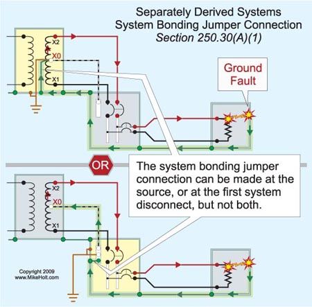
Why doesn't this same configuration apply to a grounded, separately derived system? Why does NEC require SSBJ (supply side bonding jumper) to run from the outside equipment to the first disconnect if the SBJ (system bonding jumper) is installed in the disconnect?
Why doesn't this same configuration apply to a grounded, separately derived system? Why does NEC require SSBJ (supply side bonding jumper) to run from the outside equipment to the first disconnect if the SBJ (system bonding jumper) is installed in the disconnect?