jmellc
Senior Member
- Location
- Durham, NC
- Occupation
- Facility Maintenance Tech. Licensed Electrician
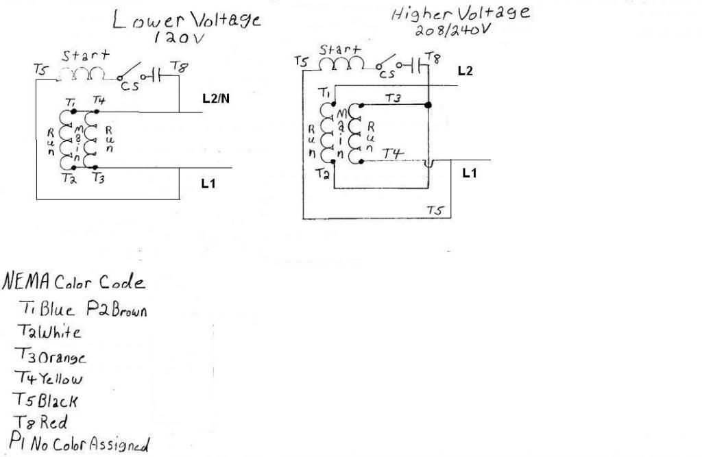
I am hooking up an air compressor that has been on 240, changing to 120. As usual, nameplate gives diagram for low/high voltage. This motor has screw terminals in wiring box, ring terminals on leads. I know for sure terminals 1 & 4 connect to windings, as 1 & 4 are always used for incoming leads. 2 & 3 are used for 2 leads each under 1 hookup & 1 & 3 leads another way.
Question is; are terminals 2 & 3 merely there to splice the leads as needed or do they connect back to the windings? Motor is very old. #2 is rusted & I may not be able to remove nut without WD 40 or such & that still may not work.
Thanks for any help.
Question is; are terminals 2 & 3 merely there to splice the leads as needed or do they connect back to the windings? Motor is very old. #2 is rusted & I may not be able to remove nut without WD 40 or such & that still may not work.
Thanks for any help.