Bedroom Recept.

Status
Not open for further replies.

donf

Member
Educate me please.

While in my office, Directv went out. Using a NCV tester, yielded the presence of voltage on both hot and neutral. However, a meter yield 0 (zero) volts between Neutral and Hot.

When I pulled the recept., I found that there was 120v between Neutral and Ground and 120 V between Hot and ground.

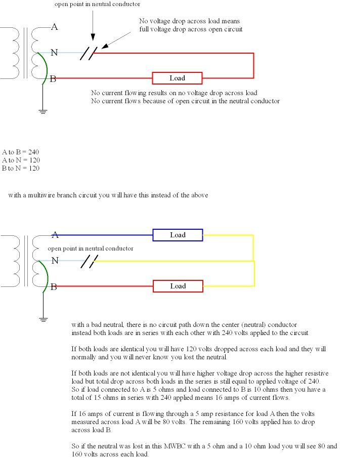
Now, if this had been a multiwire branch circuit and Neutral failed I would expect to find 240 V.

Seeing that there was only 120V I'm sure the same phase was involved but I'd like an explanation so I can pass it along during a safety segment of class that I have planned.

Don
 

Dennis Alwon

Moderator
Staff member
Location
Chapel Hill, NC
Occupation
Retired Electrical Contractor
You can have 120v reading if the hot or neutral is compromised however if there is a load on it then the voltage would drop to zero. \
How did you test the voltage when you pulled out the recep. ?????
 

hurk27

Senior Member
You can have 120v reading if the hot or neutral is compromised however if there is a load on it then the voltage would drop to zero. \
How did you test the voltage when you pulled out the recep. ?????

If the hot was lost then there would be 0 volts to anything, if the neutral was lost there would be 0 volts between the hot and neutral but you would have full volts between either hot or neutral to ground, a load before or after this point but after the point of the neutral loss will only serve to provide a connection between the hot and neutral which is why the neutral voltage will rise to the potential of the hot.
 

kwired

Electron manager
Location
NE Nebraska
Does this help explain things?

openneutrals_zps39c72e25.jpg


I should add:

If it were a multiwire branch circuit whether or not you measure 240 volts depends on exactly where you are measuring and what resistance of each load is. You will measure anywhere between 0 and applied voltage of 240. If measuring across just one of the loads you will measure voltage drop across that particular load only. If too much voltage burns out one of the loads then you will measure zero across the other load, 120 to ground, and 240 across the burned out load.
 
Last edited:

kwired

Electron manager
Location
NE Nebraska
yep much better then my words could ever:thumbsup:

Lately it seems I been having a problem getting out the thoughts in my mind and putting them into words, does this mean I'm starting to catch the Old Farts Syndrome:weeping:

I wasn't really sure how to explain it very clearly myself without some help from a drawing, especially when you don't know how the person reading will interpret what was said.
 

Dennis Alwon

Moderator
Staff member
Location
Chapel Hill, NC
Occupation
Retired Electrical Contractor
I did not mean the hot was open but that it was compromised. It can be connected by a hair and allow a reading but as soon as something is plugged in the voltage will read zero/
 

hurk27

Senior Member
I did not mean the hot was open but that it was compromised. It can be connected by a hair and allow a reading but as soon as something is plugged in the voltage will read zero/

A'hhhh ok I had the OP in mind when I made my responce and was thinking of a lost neutral as in what George posted, wasn't thinking of a high impedance loss where like a phantom voltage when a load is applied to the circuit the voltage goes away.
 

donf

Member
Mistaken information

Mistaken information

I believe I described the branch circuit incorrectly. It is not a MWBC.

It is a single 20 amp circuit using an 10/2 w/ ground cable.
 

hurk27

Senior Member
I believe I described the branch circuit incorrectly. It is not a MWBC.

It is a single 20 amp circuit using an 10/2 w/ ground cable.

We understood that what you are describing at least it was clear to me, and I think it was to most of us even though some responded with diagrams that included multi-wired circuits.

the reason you got 120 volts between the neutral and ground as well as between the hot and ground was the ground is still connected to the neutral back at the panel, the neutral to ground voltage is because there is still a load connected to the neutral and hot and you are seeing the voltage of the hot on the neutral through this load, this is because there is a loss of the neutral connection at some point between this receptacle and the panel.

If you look at the top diagram in post 5 he is showing the hot neutral in red from the neutral side of the load (the rectangle box) back to the point of the broken connection, if you were to put an meter any where on the red neutral and the green equipment grounding conductor you will be reading the voltage of the hot through the load, remove the load and this voltage will all but go away, if you are using a high impedance meter such as a DVM you could still see a phantom voltage but that is another story as you should be using a loaded meter such as a wiggy that adds a load to the circuit you are measuring.

A quick way to find this lost neutral connection if it happened at a receptacle is to use a three light tester and plug in a light that will let you know when power comes back on, then go to each receptacle on this circuit plug in the tester and use it to wiggle the receptacle, if you get to the receptacle that when wiggling it make the light turn on or flicker then you found the receptacle with the bad neutral connection, also make sure you do this to receptacles that are still working that are on this circuit as the bad connection can be at the receptacle just ahead of the first one the has a lost neutral, also if all receptacles on the circuit have a lost neutral then check the neutral of this circuit at the breaker panel as it could have lost its connection there.
 

hurk27

Senior Member
I also saw that you were using a non-contact voltage tester, even though you did the correct thing and got a meter to confirm the indication of the NCVT I would suggest to not use a NCVT as a trouble shooting device as it can cause you to think a circuit has voltage when it doesn't, it can give to many false positives that can send you looking down the wrong road thinking you have a voltage on a conductor when you don't.

A loaded meter such as a wiggy or even better a Ideal Volt-Con that also has a continuity tester that also places a 1kΏ load on the circuit under test, this loads the circuit so any phantom voltage that can be cause by capacitance coupling to be eliminated leaving only a true voltage if one is present.
 

kwired

Electron manager
Location
NE Nebraska
I drew the two wire circuit because I was pretty sure that is what the OP was trying to describe.

I drew the MWBC because he mentioned one in the OP, and expected to see 240 volts if it was one. As I said 240 volts is applied to the MWBC and can be measured somewhere, but depending on conditions may or may not be measured at the receptacle in question. Voltage at that point could be any value between zero and 240, depending on what loads are connected.
 
Status
Not open for further replies.
Top