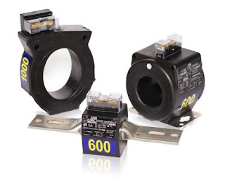
Bonding of Neutral and ground. In remote Installations

Status
Not open for further replies.

Fordean

Senior Member
Location
New Jersey
Occupation
Electrical Contractor
Im installing service. Design is as follow in pics. Ct Cab is twenty feet away. Neutrals and ground will be bonded at CT before normal way to go all the way back to switch gear. Is this permissable.

Also Have A Isolated ground. Can I terminate at the CT.

New Meter Assembly  MKH.jpg

Need to upload photo another way.
 
Last edited:

beanland

Senior Member
Location
Vancouver, WA
Metering is not NEC, it is per Utility

Metering is not NEC, it is per Utility

Consult the serving utility. CTs and metering are not covered by NEC, rather by NESC, and must be installed per Utility standards. These vary by utility.
 

augie47

Moderator
Staff member
Location
Tennessee
Occupation
State Electrical Inspector (Retired)
I agree with beanland but note that it is commonplace with all the area POCOs to allow/use the grounded conductor to bond the CT meter enclosure or any other POCO cabinet..
Equipment grounding, isolated or otherwise, is normally not introduced prior to the service cabinet here. Code not withstanding, POCO normally does not want to give you a reason to enter their enclosures
 

Fordean

Senior Member
Location
New Jersey
Occupation
Electrical Contractor
I agree with beanland but note that it is commonplace with all the area POCOs to allow/use the grounded conductor to bond the CT meter enclosure or any other POCO cabinet..
Equipment grounding, isolated or otherwise, is normally not introduced prior to the service cabinet here. Code not withstanding, POCO normally does not want to give you a reason to enter their enclosures

I understand. Not wanting access to here in situation. Now Would it be ok to Bond neutral and ground at this point. What would be the Negative side of this. Is their any hazard which I most concerned. CT back to Meter stack is Exterior. Only MDP is inside.
 

kwired

Electron manager
Location
NE Nebraska
I tried to zoom in on the image but could not read any of the print when I did so.

I am assuming the second from far right box is the service disconnect from what I can tell, and is serving the meter bank to it's immediate left, and another (possibly unmetered?) disconnect to the far right.

You are apparently adding all the equipment to the left of the mentioned meter bank but will be CT metering this load.

The question becomes where is the service point? Even though the POCO puts seals on the meters in the meter bank, in most cases that meter bank is still customers equipment and on the NEC side of the service point.

Same would apply to the CT meter equipment. It is likely on the NEC side of the service point, so separation of grounded and equipment grounding conductors should apply since it is on load side of service disconnecting means. But POCO can still lock the CT equipment cabinet as the contained equipment is essentially theirs.

Let me know if I have the arrangement of things wrong - it is too hard to read so I am just guessing at what you have.
 

Fordean

Senior Member
Location
New Jersey
Occupation
Electrical Contractor
I tried to zoom in on the image but could not read any of the print when I did so.

I am assuming the second from far right box is the service disconnect from what I can tell, and is serving the meter bank to it's immediate left, and another (possibly unmetered?) disconnect to the far right.

You are apparently adding all the equipment to the left of the mentioned meter bank but will be CT metering this load.

The question becomes where is the service point? Even though the POCO puts seals on the meters in the meter bank, in most cases that meter bank is still customers equipment and on the NEC side of the service point.

Same would apply to the CT meter equipment. It is likely on the NEC side of the service point, so separation of grounded and equipment grounding conductors should apply since it is on load side of service disconnecting means. But POCO can still lock the CT equipment cabinet as the contained equipment is essentially theirs.

Let me know if I have the arrangement of things wrong - it is too hard to read so I am just guessing at what you have.

For some reason the site has changed uploading of pictures. I dont know why it post a picture. Just trying to load a pdf. File to view.
 

Fordean

Senior Member
Location
New Jersey
Occupation
Electrical Contractor
For some reason the site has changed uploading of pictures. I dont know why it post a picture. Just trying to load a pdf. File to view.

Ok I think it was me. Found another way to up load I think.


The Dry Cleaners on right. Feeds a Remote CT already. They need more then the 200 amp avail Socket size meter stacks max at. I dont want to confuse my install on left with the dry cleaners. Its fuse at 1200. I had Utility Max KW during year for all suite. its 302KW now with the Added load I am supplying.

Public service dont like CT being used as raceway. But it customer owned. They should not have no say. I need to Isolate the Neutrals in this CT cab. I think to abide by NEC. am I correct.

View attachment New Meter Assembly 7 11 Freeho test.pdf
 
Last edited:

Smart $

Esteemed Member
Location
Ohio
Ok I think it was me. Found another way to up load I think
The picture/image in the pdf appears cropped compared to the image in the OP... but at least we can read the available annotations.

The 1200A main appears to be the service disconnect... but needs to be verified it is not a POCO-controlled or required "meter disconnect". Same goes for the disconnect to the immediate right of the CT cabinet.

Ultimately, if the service disconnect is load side of the CT cabinet, bonding is to the grounded conductor. If the service disconnect is to the line side of CT cabinet, bonding is done by EGC isolated from grounded conductor.
 
Last edited:

Fordean

Senior Member
Location
New Jersey
Occupation
Electrical Contractor
The picture/image in the pdf appears cropped compared to the image in the OP... but at least we can read the available annotations.

The 1200A main appears to be the service disconnect... but needs to be verified it is not a POCO-controlled or required "meter disconnect". Same goes for the disconnect to the immediate right of the CT cabinet.

Ultimately, if the service disconnect is load side of the CT cabinet, bonding is to the grounded conductor. If the service disconnect is to the line side of CT cabinet, bonding is done by EGC isolated from grounded conductor.

400 amp is on line side of CT. So I must Isolate Grounded conductor from EGC. ? CT come Pre bonded. Lugs.
 

iwire

Moderator
Staff member
Location
Massachusetts
If the service disconnect is to the line side of CT cabinet, bonding is done by EGC isolated from grounded conductor.

In my area that is not the case at all, the meter sockets and CT cabinets that the power company specifies will have the neutral permenantly bonded to the enclsure.

This is allowed by NEC 250.142(B) exception 2.
 

Fordean

Senior Member
Location
New Jersey
Occupation
Electrical Contractor
In my area no, we would not modify the CT cabinet, we would let the neutral remain bonded.

If I keep the Ct Neutral Bonded to cabinet. The EGC from MDP terminate their and continue or just stop their. ? They are separate from MDP to Ct.
 

kwired

Electron manager
Location
NE Nebraska
Isn't a CT cabinet nothing more than a cabinet, and you install CT's, grounding lugs, other accessories in it?

If you don't want to bond the grounded conductor you use splicing methods that are isolated from the cabinet.

You may be able to purchase cabinets with equipment already installed, and they may have a lug already bonded to the cabinet. If that is the case then attach EGC ground there and use something else for the neutral.

Most CT cabinets I have been involved with were very basic cabinet and almost everything inside is field installed.
 

kwired

Electron manager
Location
NE Nebraska
I believe there is an exception somewhere that allows neutral to be grounded to a meter socket cabinet on load side of service but requires the meter to be located fairly close to the service disconnect. But a CT cabinet I don't think would fit that exception, a 400 amp meter socket would though. You still would need an equipment grounding conductor with the load side conductors.
 

kwired

Electron manager
Location
NE Nebraska
For some reason the site has changed uploading of pictures. I dont know why it post a picture. Just trying to load a pdf. File to view.

Use some third party site like Photobucket to post photos, the forum's tools for this stink, have limitations on file size and like to resize your image like you experienced.
 

iwire

Moderator
Staff member
Location
Massachusetts
Isn't a CT cabinet nothing more than a cabinet, and you install CT's, grounding lugs, other accessories in it?

Not in my area.

Here we must use what the power company requires and here that is a CT cabinet like this.

EMI-CT346M-400-600A-CT-cans.jpg


The neutral lugs will be directly attached to the enclosure.
 

kwired

Electron manager
Location
NE Nebraska
Not in my area.

Here we must use what the power company requires and here that is a CT cabinet like this.

EMI-CT346M-400-600A-CT-cans.jpg


The neutral lugs will be directly attached to the enclosure.
Do they have some jumper bar that bridges between the lug assemblies that the CT's wrap around?

Most of what we see around here is POCO supplied and usually POCO installed, but often is just a cabinet and they mount CT's in the field (or in the shop, but not preinstalled from mfgr.) They will pass field installed conductors directly through the CT's and make splices with Polaris taps or similar devices.
 

iwire

Moderator
Staff member
Location
Massachusetts
Do they have some jumper bar that bridges between the lug assemblies that the CT's wrap around?

AccuRange+CTs.jpg


It took a while but I found a picture of one.

The beauty of these is that I don't need the CTs on the job to do my part of the work and the power company does not need me to un-wire them if they want to replace them.

With larger services we often skip using a sperate cabinet and have the provisions for these bolt in CTs built right into the switchgear either before or after the service disconnect depending on the power companies requirements.


Most of what we see around here is POCO supplied and usually POCO installed, but often is just a cabinet and they mount CT's in the field (or in the shop, but not preinstalled from mfgr.) They will pass field installed conductors directly through the CT's and make splices with Polaris taps or similar devices.

I will find that around here in services from the 1970s or earlier.
 
Status
Not open for further replies.
Top