Conductor in parallel

Status
Not open for further replies.

Adnan Hasan

Member
Location
baghdad, Iraq
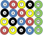
I have to connect 4 single conductors, 400 Vac, 50 Hz, of 300 mm2 per phase in parallel across 120 m length to deliver power to hospital. For 3 phases, neutral, and grounding; total single conductors will be 20 (all of same size 300 mm2). The raceway for these conductors is ventilated trough cable tray of 500 mm width.
What is the best wiring method to reduce the effect of magnetic and voltage field?

I arrange conductors in parallel as shown in the attached picture. Is it right?
 

Attachments

  • conductors in parallel.jpg
    conductors in parallel.jpg
    72.6 KB · Views: 3

Dennis Alwon

Moderator
Staff member
Location
Chapel Hill, NC
Occupation
Retired Electrical Contractor
Not sure but wouldn't it be better to bundle each set of parallel runs-- I don't use cable tray so I may be off here.
 

GoldDigger

Moderator
Staff member
Location
Placerville, CA, USA
Occupation
Retired PV System Designer
Not sure but wouldn't it be better to bundle each set of parallel runs-- I don't use cable tray so I may be off here.

From a straight E/M field argument, and assuming that the current is balanced among the parallel conductors, the layout shown will be good.
But if there is little or no neutral current (fully balanced) the result would be better if you put all the neutrals over at one edge, next to the PEs, to let you arrange the phase conductors more compactly.
Bundling each parallel set, with the three phase conductors surrounding the neutral, or bundling the phases tightly with the neutral running alongside would also be good, but would take up more space in the raceway.
The worst from an E/M point of view would be bundling all of the parallel conductors for the same phase and then laying them in.
 

GoldDigger

Moderator
Staff member
Location
Placerville, CA, USA
Occupation
Retired PV System Designer
I have to ask why you did not include the 'PE' in the mix.

That could add impedance under fault conditions.

Depends on the goal and the fault current calculation. If the impedance is low enough with the PEs off to the side, then the goal of just providing clean power with little E and M noise will be better met by keeping the non-current-carrying conductors out of the way, to get the others closer together. Same consideration applies to the neutral if it will not normally carry much current. But looking at noise induced into the conductors by an external source, keeping the neutrals symmetrical too will be best.
In some areas of a hospital, like labs, MRI machines, radiation treatment, etc. you want nearby power conductors to produce as little disturbing fields as possible, and this requires different strategies than normal power wiring.
 
Last edited:

don_resqcapt19

Moderator
Staff member
Location
Illinois
Occupation
retired electrician
Take a look at 392.20(C). It appears to me that they must be installed in groups that contain each of the phases and the grounded conductor.
 

GoldDigger

Moderator
Staff member
Location
Placerville, CA, USA
Occupation
Retired PV System Designer
Take a look at 392.20(C). It appears to me that they must be installed in groups that contain each of the phases and the grounded conductor.
I, on the other hand, would be open to the interpretation that the entire group of 20 wires constitutes one single circuit group and can/should be bound together. That would involve derating the cables, but the original drawing would require that too, since spacing was not maintained.

If avoiding derating of the conductors is essential, then binding the parallel conductors in sets of four (or five) would satisfy both requirements.
 
Last edited:

don_resqcapt19

Moderator
Staff member
Location
Illinois
Occupation
retired electrician
I, on the other hand, would be open to the interpretation that the entire group of 20 wires constitutes one single circuit group and can/should be bound together. That would involve derating the cables, but the original drawing would require that too, since spacing was not maintained.

If avoiding derating of the conductors is essential, then binding the parallel conductors in sets of four (or five) would satisfy both requirements.
I don't think so.
(C) Connected in Parallel. Where single conductor cables comprising each phase, neutral, or grounded conductor of an alternating-current circuit are connected in parallel as permitted in 310.10(H), the conductors shall be installed in groups consisting of not more than one conductor per phase,
neutral, or grounded conductor to prevent current imbalance in the paralleled conductors due to inductive reactance. ...
 

GoldDigger

Moderator
Staff member
Location
Placerville, CA, USA
Occupation
Retired PV System Designer
I don't think so.

You are absolutely correct. And if the OP is required to follow NEC, that must be followed.
On the other hand, from a strict consideration of the reasoning behind the provision, to prevent uneven current distribution caused by reactance, the original arrangement meets that goal too. But the NEC does not usually, for good reasons, allow that kind of field engineering.
 

Smart $

Esteemed Member
Location
Ohio
I'd arrange them as follows and be done with it...

groupedconductors.gif
 

m sleem

Exemplary Сasual Dating - Genuine Females
Location
Usa
Occupation
Health
I have to ask why you did not include the 'PE' in the mix.

That could add impedance under fault conditions.

All the conductors of the same circuit (line, neutral, ground) shall be contained within the same raceway, cabletray

Please look at 300.3(b)
 

Smart $

Esteemed Member
Location
Ohio
so, according to 392.20(C), PE shall not be included in the group if neutral already inside the group :?
PE (or rather EGC if compliance with NEC is spec'd) in group is neither required nor prohibited. However, if the EGC is in the grouping, I believe it cannot cause the current carrying conductors to be a greater distance apart than if the EGC were not included (not written anywhere that I know of... just a personal interpretation).

FWIW, you can install only one EGC. See 250.122(F) Because you are using mm? sized conductors, I believe the ampacity has to be determined per 310.15(C) Enginering Supervision, as the NEC only recognizes AWG and common kcmil sizes. That said, IIRC, 300mm? is just under 600kcmils, so it should be rated at least 400A @ 75?C [the common terminal temperature limit of 110.14(C) here with NRTL listed equipment]. Assuming the OCPD is 1600A, 250.122 permits one EGC sized at 4/0 AWG copper (125mm? is next common larger size)... or possibly even no wire EGC, using the tray itself as an EGC (you would have to ascertain the tray's EGC capability through manufacturer documentation or listing).
 
Status
Not open for further replies.
Top