Residential PV Wiring Errors

Status
Not open for further replies.

shortcircuit2

Senior Member
Location
South of Bawstin
Installations with transformerless inverters such as the PVI 6000 TL are being installed and connected to arrays wired as a grounded system in our area.

The PV array must be wired as ungrounded or "floating"with the transformerless inverter.

This includes:

1. Not using white colored wire in string wiring.
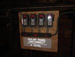
2. Any field installed DC disconnect must break both negative and positive ungrounded conductors.
3. Any string fusing must also be in both ungrounded conductors.
4. Exposed string wiring must be PV type wire.
5. PV module whips must also be PV type wire.
 

jaggedben

Senior Member
Location
Northern California
Occupation
Solar and Energy Storage Installer
Yup. What's annoying is when you are working as a subcontractor, and you are responsible for supplying the wiring, and at the last minute the contractor changes the inverter type on you.
 

ggunn

PE (Electrical), NABCEP certified
Location
Austin, TX, USA
Occupation
Consulting Electrical Engineer - Photovoltaic Systems
I have it from several sources that the most common error in installing PV (residential or commercial) is wiring AC discos backwards. The utility goes on the line side of the switch and the inverter goes on the load side. You don't want the fuses and/or blades to remain hot when the switch is open.
 

tallgirl

Senior Member
Location
Great White North
Occupation
Controls Systems firmware engineer
I have it from several sources that the most common error in installing PV (residential or commercial) is wiring AC discos backwards. The utility goes on the line side of the switch and the inverter goes on the load side. You don't want the fuses and/or blades to remain hot when the switch is open.

Depends. If it is labelled "LINE" and "LOAD" it cannot be wired for back-feeding unless it is listed for back-feeding.

In which case, you're right -- you don't want exposed parts hot -- and the part shouldn't be used.
 

GoldDigger

Moderator
Staff member
Location
Placerville, CA, USA
Occupation
Retired PV System Designer
Depends. If it is labelled "LINE" and "LOAD" it cannot be wired for back-feeding unless it is listed for back-feeding.

In which case, you're right -- you don't want exposed parts hot -- and the part shouldn't be used.

In addition to the hot parts issue, a breaker with LINE and LOAD markings which includes a shunt trip capability must not be wired with the LOAD contacts toward POCO or you risk burning out trip coils which were not designed to stay energized.
That does not mean that it will be damaged by back feed if connected with LINE toward POCO, but it would not be legal to use it that way unless so rated, as tallgirl said.
And wiring up a normal breaker with LOAD toward POCO to have the feed going in the right direction is just a wrong thing to do.
The thing which seems to cause the most confusion is that whenever the breaker is open, the inverter will not be generating any power, but POCO can still be applying voltage to their side.
 

ggunn

PE (Electrical), NABCEP certified
Location
Austin, TX, USA
Occupation
Consulting Electrical Engineer - Photovoltaic Systems
Depends. If it is labelled "LINE" and "LOAD" it cannot be wired for back-feeding unless it is listed for back-feeding.

In which case, you're right -- you don't want exposed parts hot -- and the part shouldn't be used.
I believe that applies to breakers, not discos.
 

ggunn

PE (Electrical), NABCEP certified
Location
Austin, TX, USA
Occupation
Consulting Electrical Engineer - Photovoltaic Systems
I believe that applies to breakers, not discos.
See 690.10(E) where it says breakers marked "line" and "load" may not be backfed. I have found no equivalent language pertaining to disconnect switches.
 

Q-5 Hunter

Member
Location
United States
Good stuff. I would also add, after receiving several calls about series fusing with TL's, that TL inverters still fall under the implied NEC rule of series fusing for more than 2 strings. Just because you are using a floating array doesn't mean you automatically fuse all conductors.

"What are you guys trying to do here?! This disconnect has no fuses for your TL inverter!!"
 

ggunn

PE (Electrical), NABCEP certified
Location
Austin, TX, USA
Occupation
Consulting Electrical Engineer - Photovoltaic Systems
Good stuff. I would also add, after receiving several calls about series fusing with TL's, that TL inverters still fall under the implied NEC rule of series fusing for more than 2 strings. Just because you are using a floating array doesn't mean you automatically fuse all conductors.
But it does mean that if you do need to fuse the conductors, i.e., if you have three or more parallel strings, you must fuse both the negative and the positive conductors.
 

Zee

Senior Member
Location
CA
Exactly, no fuses required until strings>2.

An interesting result with TWO strings (no more) in the field is that, if you like to install DC disconnects (say, the good ole Square D, HU361RB) (not the integrated inverter branded one) then you will need more than the three poles typically provided if you have just two strings.
So whaddya do?

1. is there a 4-pole one at 600 VDC?:?
2. Do you buy and install two DC discos?
3. I'd probably just combine on roof with 4 fuses.

Or...will there be a new need for the MC tee (Y) connectors we just finished disparaging? :)
 

shortcircuit2

Senior Member
Location
South of Bawstin
Here is a job with multiple DC disco's for 4-strings of an ungrounded array. The array is just above on the roof of the barn and this is the 1st readily accessible location. From here there is a 100+ foot run of the DC to two PVI-6000-TL inverters near the service equipment...
 

Attachments

  • Solar 015.jpg
    Solar 015.jpg
    125 KB · Views: 1

ggunn

PE (Electrical), NABCEP certified
Location
Austin, TX, USA
Occupation
Consulting Electrical Engineer - Photovoltaic Systems
Exactly, no fuses required until strings>2.

An interesting result with TWO strings (no more) in the field is that, if you like to install DC disconnects (say, the good ole Square D, HU361RB) (not the integrated inverter branded one) then you will need more than the three poles typically provided if you have just two strings.
So whaddya do?

1. is there a 4-pole one at 600 VDC?:?
2. Do you buy and install two DC discos?
3. I'd probably just combine on roof with 4 fuses.

Or...will there be a new need for the MC tee (Y) connectors we just finished disparaging? :)
Eaton makes DC discos for ungrounded DC with 2, 4, and 6 pole switches.
 

esquared

Member
The PV array must be wired as ungrounded or "floating"with the transformerless inverter.

Here is an excerpt from AE's Solaron 500 -transformerless- (when they were still called Solaron).
solaron 500.jpg

It shows only the positive being fused in one half of the bipolar array, and the negative fused in the other half of the bipolar array.

I am not certain if the topology of this inverter considers and complies with the intention of 690.35 through the use of the internal DC Contactor, but it is listed with these instructions. We can't always assume that transformless = ungrounded.

As a side note, AE's 500 1kV NX (1000V transformerless) operates on a monopole, and does require both poles to be fused in the field.
 

GoldDigger

Moderator
Staff member
Location
Placerville, CA, USA
Occupation
Retired PV System Designer
Here is an excerpt from AE's Solaron 500 -transformerless- (when they were still called Solaron).
View attachment 8464

It shows only the positive being fused in one half of the bipolar array, and the negative fused in the other half of the bipolar array.

I am not certain if the topology of this inverter considers and complies with the intention of 690.35 through the use of the internal DC Contactor, but it is listed with these instructions. We can't always assume that transformless = ungrounded.

As a side note, AE's 500 1kV NX (1000V transformerless) operates on a monopole, and does require both poles to be fused in the field.

That box inside the inverter containing the fuses is really strange. What is driving the contacts (N.O. and N.C.) inside it? And are the multiple N.O. contacts just paralleled for greater current capacity? The fact that only one of the parallel set is shown connected through the fuse to ground is also weird. This looks a little bit like a ground detector with parts missing too. :)

A transformerless inverter using a bipolar array will normally not need the array to float. One using a single-ended array is much more likely to need it to be ungrounded.
 

esquared

Member
What is driving the contacts (N.O. and N.C.) inside it?

I'm not an inverter engineer, but my understanding is that the contactor senses when array voltage is sufficient and then closes.

And are the multiple N.O. contacts just paralleled for greater current capacity?

That's my understanding.

This looks a little bit like a ground detector with parts missing too. :)

When the array is not connected to the inverter, i.e. contactor open, the neutrals of the array are connected to ground through the ground fault fuses.

A transformerless inverter using a bipolar array will normally not need the array to float.

I believe the ground reference is disconnected and the array is floating during inverter operation.
 

GoldDigger

Moderator
Staff member
Location
Placerville, CA, USA
Occupation
Retired PV System Designer
When the array is not connected to the inverter, i.e. contactor open, the neutrals of the array are connected to ground through the ground fault fuses.
I believe the ground reference is disconnected and the array is floating during inverter operation.

That looks like what they are doing alright. But given that, they are not showing any OCDP explicitly anywhere, unless the disconnects shown are assumed to be OCPD too.
When the inverter is off the disconnects are where they need to be for a grounded array, and the array is grounded.
But when the contactor pulls in the result is a single 1200 volt ungrounded array, with disconnects on both overall + and overall, as required -. But the midpoint is also carried to the inverter and back.
Off the top of my head, I am not sure how the NEC would treat that. But the 1200 volt system voltage strikes me as a real problem. (Unless the two sub-array voltages are limited to 500V max, of course.)
One of the nominal advantages of a grounded bipolar array is that no line to ground voltage will exceed 1000 volts, nor will there be more than 1000V line to line in any individual circuit going to the inverter. This simplifies meeting the insulation and other requirements while allowing a higher array operating voltage.
Once they disconnect the neutral ground, all that goes out the window. And there is no indication that there is an operating ground detector once the contactor has pulled in.
 

jaggedben

Senior Member
Location
Northern California
Occupation
Solar and Energy Storage Installer
This should probably have been its own thread. Anyway...

I believe the ground reference is disconnected and the array is floating during inverter operation.

I would be extremely surprised if that were the case. It would mean the inverter does not have the required GFDI during normal operation.

And there is no indication that there is an operating ground detector once the contactor has pulled in.

There is no indication, period, of what controls the contactors between the GFI fuses and ground. A reasonable assumption, given code and UL requirements, would be that they are closed during normal operations. Perhaps they only open when a ground fault is detected, to allow servicing of the GFI fuses without the possibility that both sides of the fuse will be energized.

Lacking a description or explanation, the diagram does not tell us much. However, I see nothing in the diagram that indicates that this topology falls under 690.35. It is a grounded system.
 
Status
Not open for further replies.
Top