ChillSparky
Member
- Location
- Golden, Colorado, USA
Details:
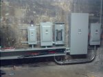
600A Service
500 MCM AL parallel
We have read read read, and re-read the handbook, two different study books and even looked online. We are still lost on how to properly bond all our conduit and enclosures on our this 600A service. We have a 600A CT on the main floor, the rest of our service is in the basement directly below it. We have installed the MBJ in our 600A Main Disconnect. Directly to the left of that service disconnect we have a gutter that feeds 1 200A fused disconnect for 1-200A panelboard, 1-200A fused at 150A to feed an RTU and 1-100A disconnect to feed an air handler. These all are fed from the feeders that are in the gutter. We have ground bushings on every side of every conduit.
Questions:
? Do we have to use one wire to bond all these bushings, and does that wire go back to the 600A disconnect?
? Can we use #1 CU to set a terminal bar inside the gutter to tap off for each disconnect after the 600A, using #6 CU? If so does this have to be a floating bar?
? Can we just jumper/bond each conduit to the respecting enclosure and call it good? Or does the bonding wire have to run through each conduit?
? Should we plan to set a grounding terminal inside the 600A, use a separate conduit and send our bonds and grounds each separately for their respective disconnects and enclosures?
I feel like I should know this without incident and feel really stupid for getting so confused and lost on this particular issue. Any help and guidance would be greatly appreciated. Sometimes one can think they understand something, then they look in the code book and then find out that they don?t and end up in a loop, searching for the correct answer. Thanks again!