DC at a 120VAC Receptacle

Status
Not open for further replies.

SG-1

Senior Member
The first picture is the filter & the second is the sine wave as seen on a Fluke 196C.

The results with the battery test with & with out the filter yielded readings of:
8.4VDC without the filter
7.63VDC with the filter
.908 just like the MAN, I mean GAR, said.

The scope shows a fairly good sine wave, a little flat on the top & bottom. That seems to be common now-a-days. There does seem to be some glitches along the curve in some spots. I have not seen this before.

I always use manual mode except by accident every now & then. I did try auto-range & it did not like the input voltage. I figure that if you are looking to measure a voltage you should know the magnitude before hand, otherwise you should probably not be measuring it. Like one of my friends & the electric fence. The meter died so young !

The readings I saw were stable. They got as high as 21+ VDC. There is some disturbance this meter is seeing & it falls back when our steel shop is on break or lunch. I will have to setup an experiment with some real DC & AC mixed to see how the meters handle it.

My next step is to check other Fluke 27 meters & see if this common or just a fluke.
 

Attachments

  • Sine_Wave.jpg
    Sine_Wave.jpg
    86.7 KB · Views: 0
  • Filter.jpg
    Filter.jpg
    64.1 KB · Views: 0

gar

Senior Member
Location
Ann Arbor, Michigan
Occupation
EE
130423-0917 EDT

It can be hard to determine the DC component magnitude of an AC + DC waveform with an oscilloscope. This is especially true if the DC component is small, or if the AC component is not symmetrical. The low pass filter means in combination with any conventional meter should always work.

.
 

gar

Senior Member
Location
Ann Arbor, Michigan
Occupation
EE
130425-0728 EDT

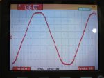
Suppose you wanted to use a Simpson 260 to measure a small DC component added to a 120 V RMS sine wave.

The Simpson has a DC meter movement with a long enough mechanical time constant that it will not follow a 60 Hz signal. It will just read a steady 0 if there is no DC component. On the 250 V DC range the input impedance is 20,000*250 = 5 megohms. Essentially there will be no more power dissipated in the series resistor and meter movement with 120 V 60 Hz applied than if 120 V DC was applied, 0.003 W. At 250 V the power is 0.013 W.

Theoretically, if you switched to the 2.5 V DC range, and applied the 120 V 60 Hz sine wave with no DC component, then the meter would still read 0 and possibly not even vibrate much. However, the series resistance is 20,000*2.5 = 50,000 ohms. This resistor and the meter movement both might burn up. Power dissipated in 50,000 at 250 V = 62,500/50,000 = 1.25 W.

Add an external 50,000 ohm series resistor, at least a 2W rating, and shunt the meter input with a 30 ufd capacitor. Now the meter becomes a 5 V DC full scale meter when on the 2.5 V range. The AC component at the meter input terminals from a 120 V input will be about 120*90/50,000 = 0.22 V. This will not power overload the meter, and easily is averaged out by the meter movement. DC voltage components from 0 to 5 V can be read.

Other voltage ranges with the external series resistance fixed at 50,000 ohms will not have the 2 to 1 scaling factor.

.
 
Last edited:
Status
Not open for further replies.
Top