Crest Factor & Harmonic Distortion

Status
Not open for further replies.

SG-1

Senior Member
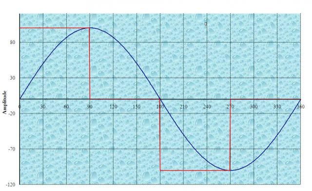
I am reading an unstable crest factor between 1.4 & 1.6 on a Fluke 289 DMM. I understand as the number gets greater than the square root of two the wave gets pointy, as the number goes lower the wave appears flattened.

Is there any way to determine the % of harmonic distortion from the crest factor of a sine wave ?
 

Besoeker

Senior Member
Location
UK
I am reading an unstable crest factor between 1.4 & 1.6 on a Fluke 289 DMM. I understand as the number gets greater than the square root of two the wave gets pointy, as the number goes lower the wave appears flattened.

Is there any way to determine the % of harmonic distortion from the crest factor of a sine wave ?
As far as I'm aware, not from the crest factor alone. The waveform could be almost any shape.
 

Sahib

Senior Member
Location
India
Is there any way to determine the % of harmonic distortion from the crest factor of a sine wave ?
The present state of electrical science is not able to answer your question. However whether a given sine wave is excessively distorted or not may be determined by its crest factor and this should be counter checked by another IEEE method for the same purpose and more conservative value of the two should be chosen as a measure of the distortion of the wave.
 
Last edited:

Besoeker

Senior Member
Location
UK
The present state of electrical science is not able to answer your question.
It isn't a limitation of the state of science. There simply isn't enough enough information to make the determination.

However whether a given sine wave is excessively distorted or not may be determined by its crest factor
If I gave you two waveforms, one with a crest factor of 1 and the other SQRT(3), which do you think is the more distorted?
 

GoldDigger

Moderator
Staff member
Location
Placerville, CA, USA
Occupation
Retired PV System Designer
If I gave you two waveforms, one with a crest factor of 1 and the other SQRT(3), which do you think is the more distorted?
Which of course leads inexorably to the question of how you measure distortion. :)

Even if you take a sine wave as the reference standard (crest factor 1.414 = SQRT(2)), how you value different types of distortion.
One standard measure is total harmonic distortion, THD.
The other unavoidable question is what does the waveform you describe with SQRT(3) crest factor look like. There are an infinite number of possibilities.
The only waveform with a crest factor of 1 is a square wave. However, that could be a square wave of any duty cycle if you are willing to allow DC components.
For a 50% duty cycle square wave, THD would be ~44%.

For a triangle wave with duty cycle 50% (the simplest, most familiar waveform with a crest factor of SQRT(3)), THD is ~12%.

And in return for your question, I have another:
If you have two waveforms with crest factor SQRT(2), are they equally perfect or equally distorted sine waves? (I am pretty sure which two examples I am thinking of.)

(BTW, I am allowing a DC component)
 

Besoeker

Senior Member
Location
UK
Which of course leads inexorably to the question of how you measure distortion. :)
I don't know how everyone else does.
My method is to capture the waveform on a digital storage oscilloscope, download it and use FFTs to get the harmonic spectrum.

Even if you take a sine wave as the reference standard (crest factor 1.414 = SQRT(2)), how you value different types of distortion.
One standard measure is total harmonic distortion, THD.
I usually look at two or three main things.
How the individual harmonics as calculated above react with other connected equipment on the supply at at the point of common coupling - the PCC.
Calculate filter values for mitigation if deemed necessary.
I then look for any potential resonances with the supply using admittance calculations.
Sounds more complicated than it is.

Here's one I prepared earlier:


The other unavoidable question is what does the waveform you describe with SQRT(3) crest factor look like. There are an infinite number of possibilities.
Of course there are. That was the point I was trying to get across to the maharajah.

And in return for your question, I have another:
If you have two waveforms with crest factor SQRT(2), are they equally perfect or equally distorted sine waves? (I am pretty sure which two examples I am thinking of.)
They could be either or neither.

Here are a couple of waveforms with the same SQRT(2) crest factor.


I'll let you draw your own conclusions...
 

Sahib

Senior Member
Location
India
SG-1:
By now, you would have realized that % harmonic content of a sine wave is best determined by first having the wave at your disposal, because the crest factor is independent of the harmonic content of the wave. However the ratio '1.414/wave crest factor' is useful to determine whether there is harmonics in a sine wave in the absence of instrumentation to trace the curve. It should be compared with the value by method in ANSI/IEEE Std C57.110 1986 and more conservative of the two to be take as a measure of harmonic content of the wave.
Perhaps your aim is to find the derating factor for the harmonic loads on an existing transformer. In that case the above-mentioned method may serve you.
 

SG-1

Senior Member
Here is the wave, I think the unstable crest factor reading is caused by the glitches, vertical portions of the wave. The concern is the effect this may have during dielectric testing.

I thank everyone for your responses.
 

Attachments

  • Sine_Wave.jpg
    Sine_Wave.jpg
    86.7 KB · Views: 0

Besoeker

Senior Member
Location
UK
SG-1:
However the ratio '1.414/wave crest factor' is useful to determine whether there is harmonics in a sine wave in the absence of instrumentation to trace the curve.
I should have thought that the waveforms I presented would have disabused you of that notion. A pure sine wave and a rectangular waveform both have the same crest factor.
No harmonics in one. Plenty in the other.
My simple point is that you can't simply construe a lot about harmonic content from just crest factor.
 

Besoeker

Senior Member
Location
UK
Here is the wave, I think the unstable crest factor reading is caused by the glitches, vertical portions of the wave. The concern is the effect this may have during dielectric testing.
.
A couple of observations.
The fundamental waveform has flattened tops.
That's indicative of third harmonic content. Much single phase electronic kit produces that. Not a lot from any single item but huge numbers of them......
The notches are typical of commutation notches three phase SCR kit.


.
 

Sahib

Senior Member
Location
India
I should have thought that the waveforms I presented would have disabused you of that notion. A pure sine wave and a rectangular waveform both have the same crest factor.
No harmonics in one. Plenty in the other.
My simple point is that you can't simply construe a lot about harmonic content from just crest factor.
If crest factor is not up to the mark in determining the harmonic content of a wave, I already suggested to use the method in ANSI/IEEE Std C57.110 1986. The converse could also be true in other cases.
 

Sahib

Senior Member
Location
India
Here is the wave, I think the unstable crest factor reading is caused by the glitches, vertical portions of the wave. The concern is the effect this may have during dielectric testing.
Since the vertical portion of the voltage wave is flat, it can not used for dielectric testing. It is because the dielectric is subjected to the maximum stress at the peak of the voltage wave. So it is suggested to use an equivalent DC voltage.
 

Besoeker

Senior Member
Location
UK
If crest factor is not up to the mark in determining the harmonic content of a wave,
It isn't as has been clearly demonstrated.
I already suggested to use the method in ANSI/IEEE Std C57.110 1986. The converse could also be true in other cases.
I'm not familiar with that standard. Perhaps you could kindly explain or quote what exactly the method is?
 

Besoeker

Senior Member
Location
UK
For the cases you put up.
It isn't unique. In fact, far from being so. But, even if it were, it would still be sufficient to demonstrate that you can't infer a harmonic spectrum from the crest factor.

I would like to advise you to purchase the standard, go through it and then put up your comments.
And I would like to advise you to explain it since you cited it.
 

Sahib

Senior Member
Location
India
It isn't unique. In fact, far from being so. But, even if it were, it would still be sufficient to demonstrate that you can't infer a harmonic spectrum from the crest factor.
Not harmonics spectrum; just extent of harmonic distortion.

And I would like to advise you to explain it since you cited it.
I do not think it is possible to convince you.:happysad:
 

charlie b

Moderator
Staff member
Location
Lockport, IL
Occupation
Retired Electrical Engineer
Sahib and Besoeker: Please keep your comments technical and your tone professional. If you wish to wrangle with each other, try communicating by PM.
 

Besoeker

Senior Member
Location
UK
Sahib and Besoeker: Please keep your comments technical .
My posts have been technical. See post #6 for example. And maybe #10.
I don't see anything of comparable technical merit being reciprocated.
Do you?
 
Last edited by a moderator:

SG-1

Senior Member
Since the vertical portion of the voltage wave is flat, it can not used for dielectric testing. It is because the dielectric is subjected to the maximum stress at the peak of the voltage wave. So it is suggested to use an equivalent DC voltage.


Sahib, dielectric testing is governed by IEEE Std 4-1995. Look at section 6.1.1
 
Status
Not open for further replies.
Top