SG-1
Senior Member
- Location
- Ware Shoals, South Carolina
And he hasn't paid my bill yet!!
Just put that on my tab, please.
And he hasn't paid my bill yet!!
Since you are looking at the supply voltage from the grid (yes?), it is possible that the bigger generators of third harmonics along with other higher odd harmonics (such as rectifiers and switching mode power supplies) have a third-harmonic-suppressing distribution transformer or two between them and you. That leaves the fifth harmonic, even though it may have been lower in amplitude at the source, to be dominant.
Plus what Besoeker said.")
130415-0841 EDT
SG-1:
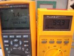
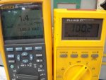
To get a reasonably clean sine wave from my 60 Hz power I used 5000 ohms and 3 ufd as a filter, 3 db point 10 Hz. Then I read the Beckman RMS and Fluke 27 meters simultaneously at the filter output. The input to filter was in the 10 V range. The capacitors were polystyrene which are a very low dissipation factor device.
With a filter like this and the parallel measurement you can see if there is a calibration difference between the meters with a pure sine wave input. If the two meters are different, then the ratio of the readings can be applied to your direct line measurements to see if the difference in readings is a result of the waveform distortion, or just because of the scaling difference.
The tests with and without the filter should be run at about the same voltage. You do not need polystyrene capacitors, just good paper, Mylar, or polypropylene.
.
130515-2355 EDT
SG-1:
Capacitor across meter input and the resistor in series. A 0.5 ufd might have been a better choice or cascading several stages. But I got the result I wanted by reducing the harmonics relative to the fundamental. A high Q LC at resonance would be better.
.
The Fluke 289 is a true RMS meter.SG-1:
Since you have harmonic problems, I think you need to use a true RMS meter for measurement of test voltage.....
My next step is to verify the Fluke 289 reading by other means.
If the peak voltage is the most important criteria for SG-1's test, then he needs a peak reading meter.Since you have harmonic problems, I think you need to use a true RMS meter for measurement of test voltage. Also, check that the crest factor of the test voltage is within [(square root 2) plus or minus 5%]. Then the peak of the applied test voltage= Its RMS value/1.414 for your testing purpose.
If the peak voltage is the most important criteria for SG-1's test, then he needs a peak reading meter..
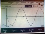
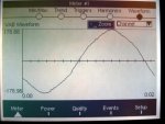
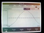
A flattened sine wave, which is what SG-1 and all the rest of us have, will have a smaller peak value than predicted from 1.414 * the RMS voltage of that waveform. For example on a square wave, a very flattened sine wave, the peak value equals the RMS value..
I believe you meant to say RMS value * 1.414 .
.
It does not matter for SG-1's high voltage test, if its crest factor is within square root of 2 plus or minus 5%.Eor my flattened sine wave there appears to be around a 1 V lower peak than predicted from 122.6 V RMS * 1.414 .
.
See post #6.It does not matter for SG-1's high voltage test, if its crest factor is within square root of 2 plus or minus 5%.
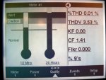
Besides the crest factor being within 5% of the square root of two, the wave is considered acceptable if the total harmonic distortion is 5% or less.
That was the point I made too.So the answer to the OP's question:no.
That was the point I made too.
It does not matter for SG-1's high voltage test, if its crest factor is within square root of 2 plus or minus 5%.
Best not go there....But sahib was correct when he made the point with respect to a sine wave with a flat top:
Finally the answer to the question you posed in the OP:
If the crest factor is within 5% of the square root of two, the total harmonic distortion would be within 5% for a nearly pure sinusoidal wave.
This answer is based on page no 30 para 4 of 'High voltage Engineering' in http://bib.convdocs.org/v4887/?download=1