Hey guys, I have a customer with some unique requirements to control his lights. I'm planning on putting a timer and a motion in parallel with the motion being ran through a holding contact on the lighting contactor. My question is with the timer and motion being in parallel the "load" contacts of the timer / motion will be hot at times when the device's contacts are open. Is this a code violation?
If interested this is how it will work:
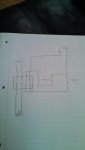
Push timer: contactor pulls in for 10 minutes including the holding contact activating the motion circuit
Motion on court: Motion on court within 10 minutes continues to hold contactor closed
No motion and timer expired: contactor opens and lights go off
Lights stay off until timer is pushed again
If interested this is how it will work:
Push timer: contactor pulls in for 10 minutes including the holding contact activating the motion circuit
Motion on court: Motion on court within 10 minutes continues to hold contactor closed
No motion and timer expired: contactor opens and lights go off
Lights stay off until timer is pushed again