bgelectric
Senior Member
So i have a scenario im confused about.
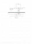
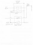
Plans call to wire 3 out of ten lights to existing life safety circuit.provide emergency shunt relay to bypass local switching. Life safety circuit is obviously on a different circuit than general lighting. I purchased a gr2001 to accomplish this. The diagram for the relay show normal power energizing coil and emergency power going though the contacts in parallel with the switch. How do i accomplish this when the switch is shown drawn in parallel with the emergency power not normal power? Its an existing building with normal power feed ing the lights..
Plans call to wire 3 out of ten lights to existing life safety circuit.provide emergency shunt relay to bypass local switching. Life safety circuit is obviously on a different circuit than general lighting. I purchased a gr2001 to accomplish this. The diagram for the relay show normal power energizing coil and emergency power going though the contacts in parallel with the switch. How do i accomplish this when the switch is shown drawn in parallel with the emergency power not normal power? Its an existing building with normal power feed ing the lights..
")