I had a situation where a mis-wired 3PH/5W cord connector (the neutral was swapped with one of the phases) resulted in 208V between the phase and neutral slots in a 1PH/3W (i.e. Phase, Neutral and Ground slots) receptacle.
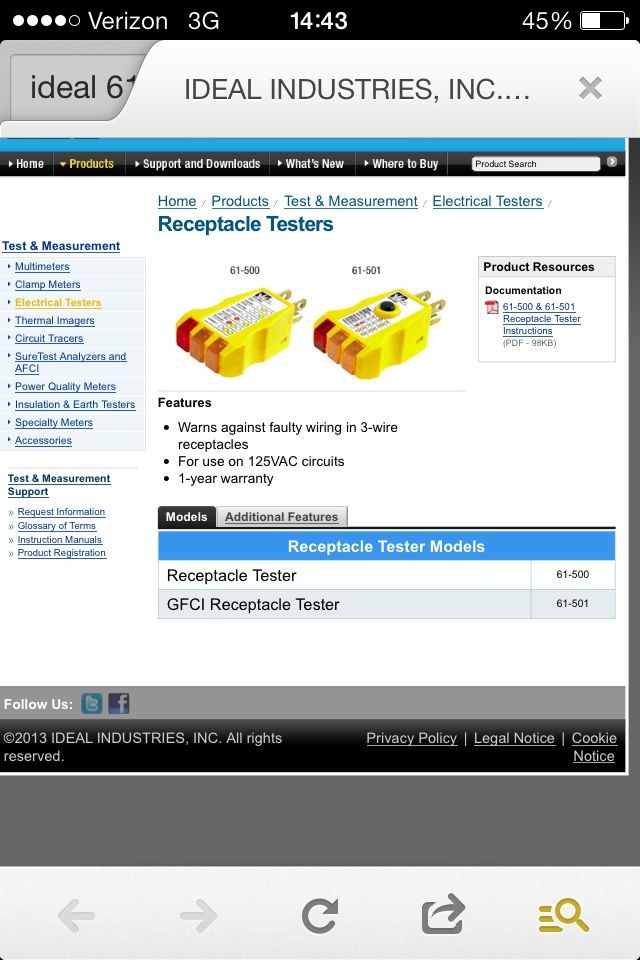
Most of the receptacle testers I've seen (such as the Ideal 61-500) seem to say they are rated for ~120V circuits...I have not found a specification sheet that says what voltage they can actually safely handle.
I know that these testers are not designed to test for "multiple hots" per se, but is it safe or could they be damaged when plugging into a receptacle that is operating on 208V as described?