Connect multiple DC sources to common ground

Status
Not open for further replies.

gar

Senior Member
Location
Ann Arbor, Michigan
Occupation
EE
151209-2010 EST

jfouts:

Rereading your original post and looking at your circuit diagram I am confused.
Each lamp has its own 12VDC source voltage.
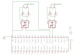
What does this mean? Your drawing shows a common negative rail for all of the lamps. If the drawing is correct, then that means all the 12 VDC voltage sources have a common reference point, and then they are not isolated.


Also in the first post.
Typically I would connect all grounds together for a single common ground, but since these lamps are being fed from multiple different pieces of equipment on their own isolated circuits, should I be concerned about connecting all of my grounds together?
This statement does not correspond with your drawing.


Suppose that your different pieces of equipment are isolated from each other, then how isolated?

Suppose highly isolated, then what unintended consequences might result from connecting their commons together?

I would, as I said before, use an optical coupler for communicating the lamp status to the Rasberry. This introduces only a few picofarads of coupling between the different pilot lamps. Wiring may create more coupling than the optocouplers.

Another consideration on your voltage regulator approach is the output voltage tolerance of the regulator, and how much overvoltage a Rasberry input can tolerate.

.
 

SceneryDriver

Senior Member
Location
NJ
Occupation
Electrical and Automation Designer
I apologize for not getting back to this sooner.
I kept waiting for an email notification that someone had posted to this thread :)


I see that I should have been more descriptive in my original question.


Yes, when I used the term ground I was not speaking of earth ground, but rather DC Negative.


While I have not yet actually visited the site that I will be installing at, if memory serves correctly the DC circuits in PLC's are bonded to the chassis, and presumably the chassis is bonded to earth ground.


This project is for a radio repeater station located at the top of our highest surrounding mountain.
Since the site is usually covered in snow, I was hoping to prep the project as much as possible in hopes of making it a one trip visit.


The station is run by a generator.


I mainly want to grab the generators 'low fuel' indicator lamp signal.


Attached is a quick draw of the circuit using a limited component library.


mgookin,
Thanks for your examples of car & PC. That made perfect sense.


jaggedben,
Polarities changing should not be an issue.


SceneryDriver,
Thank you for mentioning noise. Since this is a radio station, and all of the equipment is in relatively close quarters noise is likely to be an issue, and I had intended on using UTP. I will switch it to shielded.
Working up a board using relays may be a safer option and I will do a test run with them.
As far as Pi not being designed for industrial, can you recommend a microcontroller type other than custom building one?


gar,
I dont have a circuit diagram for the equipment yet, but as I understand it:
The generator powers the building.
Some of the equipment such as the radios run directly off of the generator.
Some of the equipment runs off its own dedicated 12v battery.
All of the 12v batteries pull a trickle charge from the generator.
There is a panel with switches, buttons & lamps.
This panel lights a lamp when there is a fault, while the buttons/switches allow you to acknowlege alarms or turn on/off/restart equipment.
Perhaps PLC was the wrong term since ive never actually seen the unit in person.
When I saw it poorly taken picture of it, it looked like an old school PLC, not that new fancy touchscreen business.
I chose a 3.3v regulator(LD1117) for the Pi inputs because I am not a fan of burnt Pi, and I had some on hand from a previous project.
I like the idea of using the optocoupler & will look into that further.


Thanks for all of the replies & Thank you for having me here!

As far as what to use, look for something from the industrial control world. Arduinos are cute, and can be useful in certain situations. In the entertainment industry, we occasionally use an Arduino or a BASIC Stamp to do things like controlling RC hobby servos for animatronic effects. PLCs aren't so good at variable duty cycle PWM that RC servos need. Though opinions vary, I'm of the belief that they're mostly hobbyist-grade gear, and have no place where life and limb and other equipment is at stake.

Even if you subscribe to the "Arduinos are as good as PLCs" argument, consider this:

You and I need to control a project. You choose an Arduino and I choose a PLC. The project in question could use either successfully.

When your Arduino comes in the mail, you pull it from the box, grab a piece of perf board or a proto-shield, and begin soldering components to create an interface to the outside world. This is after you've breadboarded your circuit and made sure it will work. After some time, you now have a one-of-a-kind interface card that lets your Arduino control something larger than an LED. NOW you get down to programming, testing, and debugging. Provided you haven't made a soldering error, your project now works, but how do you mount it in your control cabinet? They don't come with DIN rail mounts, so you have to fab those too. What happens if you have a hardware failure? You're back to the lab bench to fire up the soldering iron again.

I have chosen a PLC. I pull it out of the box, clip it onto the DIN rail in my cabinet, feed it 24v power, land the I/O on the SCREW TERMINALS (no soldering required) and do my programming. While you're still soldering your custom I/O card, I'm done with everything and at the bar having a beer.
beer.gif
If I have a hardware failure (probably less likely in a designed and tested commercial product) I can have another one overnight. I reload the program, and I'm done with the repair.

Also beware of Cletus and Bubba. They're the neck-down hammer jockeys that will be tasked with repairing and maintaining the equipment into which you've placed an Arduino. How likely is it that your hand-soldered I/O board and open PCB will survive Cletus and Bubba's gentle ministrations?
smash.gif


BASIC Stamps, Arduinos, and PIC microcontrollers all have their place. They're a fantastic tool for teaching people, kids specifically, the basics of electronic and coding theory. A PLC is, at its most basic, nothing more than a microcontroller that's been armored against the real world.

If you have thousands of copies of a thing to make, a microcontroller makes economic sense; you can design your control board to EXACTLY your specs. If you need one or a few, and need it to survive an industrial environment, be easy to maintain and repair/replace, then the PLC is your friend.

Consider also who can/will support this thing in the future. PLC's have lifespans and support usually measured in multiple decades. How's your Arduino going to fare when it comes time for someone else to support the hardware and code, years from now?

AutomationDirect has a line of PLC's called the Click. Cheap, easy to learn, free programming software, and designed for an industrial environment. The new ones even have Ethernet, though I don't believe email is supported yet.

http://www.automationdirect.com/adc...ers/CLICK_Series_PLCs_(Stackable_Micro_Brick)

AD's DirectLogic PLCs can have an Ethernet card added, and they can send email based on program conditions. Hardware is slightly more expensive and the programming software costs $$, but they are more capable.

http://www.automationdirect.com/adc...)/DirectLogic_06_(Expandable_Micro_Brick_PLC)


SceneryDriver
 

iwire

Moderator
Staff member
Location
Massachusetts
Also beware of Cletus and Bubba. They're the neck-down hammer jockeys that will be tasked with repairing and maintaining the equipment into which you've placed an Arduino. How likely is it that your hand-soldered I/O board and open PCB will survive Cletus and Bubba's gentle ministrations?

:thumbsup:

Cletus and Bubba are just some of the reasons I do not like to do unusual installations. I think it is a disservice to the customer to design and install something that will be difficult to service in the future.
 

SceneryDriver

Senior Member
Location
NJ
Occupation
Electrical and Automation Designer
:thumbsup:

Cletus and Bubba are just some of the reasons I do not like to do unusual installations. I think it is a disservice to the customer to design and install something that will be difficult to service in the future.

I wonder if the OP will post back and let us know how he made out. This is interesting to me, since I deal with the small controller and small scale automation world quite a bit.


SceneryDriver
 

jfouts

Member
Location
Union, OR USA
I am Cletus & Bubba's older brother with really fat fingers

I am Cletus & Bubba's older brother with really fat fingers

Thanks again for all of the replies. Ive been out for the holidays.

I went ahead and built/tested successfully the prototype using the optocouplers.
I went this route to prevent ant any possible backfeed/damage/interference to the sources.
I tested only on the bench, while using multiple power supply's.
The solution worked great & I was able to receive an email every time an alarm light lit. :)

My original question about combining grounds(or DC negatives) was to ease prototype board building while connecting all of the voltage regulator grounds together.
Just for giggles, after testing I did connect the grounds(DC negatives) of the two alarm sources and saw no ill effects. So presumably connecting these grounds would have been fine.

However, after doing all of this and before visiting the site, I received some better pictures which has caused me to pretty much scrap this method altogether :(

The alarm panel appears to be mostly sealed and stringing new wires from it for each alarm now appears to be counter-intuitive as the alarm panel has a modbus connection.

I have integrated the modbus library into my Pi and am now working on the decryption & logic of the modbus data feed.
I feel confident that physical installation will be a one trip process.
My only concern now is that I do not have a modbus data feed to test with, so I will likely need to do some remote reprogramming to get things fully working as desired.

As for Cletus, Bubba and myself...
I am the customer and seldom let Cletus and Bubba touch anything of mine, so not too worried about my fat fingered siblings messing things up. Its all me.

I have also found that the equipment manufacturer offers an optional modbus converter which converts modbus signals to ethernet with a $600 price tag, but still requires an owner provided PC to send out email/text notifications.
I figured since I need a PC (or Pi) anyway why not eliminate the optional converter and translate the data directly using the Pi.

Schematic below was for the successful method using optocouplers
 

Attachments

  • MTEM.jpg
    MTEM.jpg
    13.9 KB · Views: 0

jfouts

Member
Location
Union, OR USA
Hardware failure

Hardware failure

...and for hardware failure:
Once this method is setup (no breadboards required), the entire OS & program are stored on SD card which runs the Pi.

A hardware failure would at worst require a replicated SD card plugged into a new Pi.
Overnight replacement cost $35 + fuel to get up the mountain. Time spent should also be factored in but this is a job that even Cletus or Bubba could do.

In our area, it is a minimum of $1500 to get a PLC guy out even if it only takes him 10 minutes onsite, plus the cost of the overnight parts.
 

SceneryDriver

Senior Member
Location
NJ
Occupation
Electrical and Automation Designer
Thanks again for all of the replies. Ive been out for the holidays.

I went ahead and built/tested successfully the prototype using the optocouplers.
I went this route to prevent ant any possible backfeed/damage/interference to the sources.
I tested only on the bench, while using multiple power supply's.
The solution worked great & I was able to receive an email every time an alarm light lit. :)

My original question about combining grounds(or DC negatives) was to ease prototype board building while connecting all of the voltage regulator grounds together.
Just for giggles, after testing I did connect the grounds(DC negatives) of the two alarm sources and saw no ill effects. So presumably connecting these grounds would have been fine.

However, after doing all of this and before visiting the site, I received some better pictures which has caused me to pretty much scrap this method altogether :(

The alarm panel appears to be mostly sealed and stringing new wires from it for each alarm now appears to be counter-intuitive as the alarm panel has a modbus connection.

I have integrated the modbus library into my Pi and am now working on the decryption & logic of the modbus data feed.
I feel confident that physical installation will be a one trip process.
My only concern now is that I do not have a modbus data feed to test with, so I will likely need to do some remote reprogramming to get things fully working as desired.

As for Cletus, Bubba and myself...
I am the customer and seldom let Cletus and Bubba touch anything of mine, so not too worried about my fat fingered siblings messing things up. Its all me.

I have also found that the equipment manufacturer offers an optional modbus converter which converts modbus signals to ethernet with a $600 price tag, but still requires an owner provided PC to send out email/text notifications.
I figured since I need a PC (or Pi) anyway why not eliminate the optional converter and translate the data directly using the Pi.

Schematic below was for the successful method using optocouplers

If you need a MODBUS data generator for bench testing, have a look at MODSCAN.

http://www.win-tech.com/html/demos.htm

I've used it for years to test PLC setups. It works with both MODBUS RTU (serial) and MODBUS TCP (Ethernet).

If you need to convert between the RTU and TCP flavors of MODBUS, these work well:

http://www.automationdirect.com/adc...al/Serial_Isolators_-a-_Converters/MB-GATEWAY

I agree that Pi's are a good fit for applications that require data manipulation, provided they only talk over Ethernet and USB. Just make sure to put in a case to protect it. Do you have any concerns regarding ambient temperature? The Pi isn't rated to the extreme temperatures that most industrial controllers are.


SceneryDriver
 
Status
Not open for further replies.
Top