
Eduardo Maun
Member
- Location
- Qatar
Confused about the two name,do they have the same or another meaning?
Thank you.
God Bless...
Thank you.
God Bless...
Confused about the two name,do they have the same or another meaning?
Thank you.
God Bless...
Well a electrical plan is your contract drawnings by engineer and a electrical layout is your cad drawnings or construction drawnings Bim drawnings which show how you are going to do your underground or over head your actual layout of cordinated work of conduit routes and racks or raceways .
Which is something a electrical engineer cant do electricians only do layout work . Meaning we use the electrical plan and then route our conduits because a engineer doesnt do that for us.
....
Well Cadpoint at our work place which is electrical construction we call a electrical plan a engineered contract drawning and a electrical layout is ours so whats your point . Our layout is CAD and BIM 3 d drawnings And we use a trimble to do our field points for all electrical layout from Auto cad .
Thats the way i see it contract drawnings are just a set of electrical plans we look at them correct them and revise them for the engineers then we layout our work to build it our way after all ther mistakes are found .
Thats about how i see it the OP asked a question and we answered it .
If you look at his profile hes a CAD tech so i think he knows what CAD is .
Oh yes we can, and sometimes we have to. On a recent project, I did the layout for a significant conduit run. Not all runs, but one in particular. I had to, because there was limited space to get from one floor to the next, and I had to coordinate the space usage with the mechanical and plumbing engineers.(layout) . . . is something a electrical engineer can't do; electricians only do layout work .
Oh yes we can, and sometimes we have to. On a recent project, I did the layout for a significant conduit run. Not all runs, but one in particular. I had to, because there was limited space to get from one floor to the next, and I had to coordinate the space usage with the mechanical and plumbing engineers.
Most of the time, my drawings will (as you suggest) only show the points at which electrical components are to be located, leaving the actual conduit routing to the electrician. But don't tell me I don't know how to do it.
In my world, an "electrical plan" would show the entire floor as an architectural background, and I would place symbols for the locations of the electrical equipment (e.g., receptacles, luminaires, motors, panels, disconnect switches). I use the phrase "electrical layout" in the context of an enlarged plan that shows only a single electrical room, and that shows the locations of panels within that room, along with the space reserved for working clearance.
Confused about the two name,do they have the same or another meaning?
Ohmhead, most of the time I will not show any conduit routing. I only do that on large projects with complicated interfaces among disciplines.
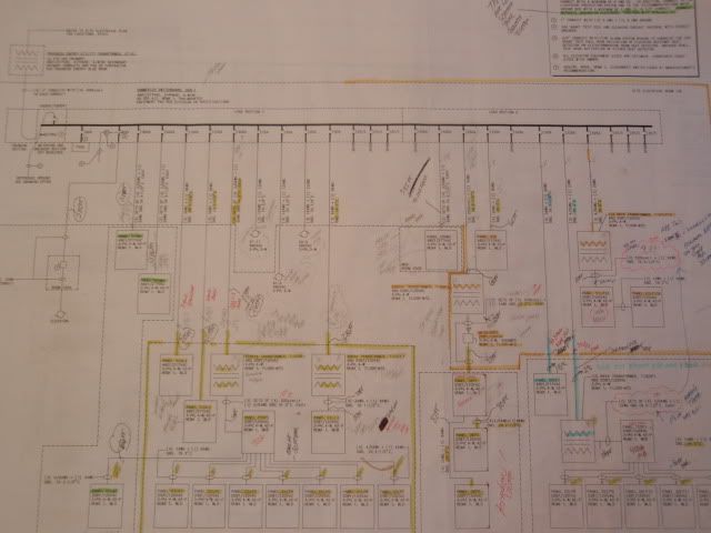
Usually, I will have riser diagrams (like the one you showed), and floor plans (that show any panels that go into corridors), and enlarged floor plans (that show how to lay out panels inside electrical rooms). I would never leave that last thing to the electrician. I know you are capable. But I believe it to be my duty to prove that the number of panels I want to put into a room can actually fit into that room, and still have the required working clearance in front of each. I don't even have my CAD group do that work for me; I do my own layouts in CAD. That is because I will keep flipping things around and moving panels across the room and doing whatever is necessary to get things to fit.
In my area the 'E' prints show the circuitry and a general idea of where the equipment will be.
On the other hand the 'A' prints will not show any circuitry but they will show specific locations of equipment.
So I guess you could call the E prints the plan and the A prints the layout.
Bob, I think you may have to interchanged the meaning of these 2 letter code, A and E. Since Layout is the one containing those circuitry, homerun of circuitry, etc...But Plan shows specific locations of equipment, general notes, specifications and drawing details of equipment that will be plan to install.
")