cosmicelectric
Member
- Location
- Oceanside, CA
- Occupation
- Contractor
Hello all,
I was recently contracted to install a piece of equipment that needs to be protected by means of isolation. I plan to do this via a transformer. I have experience installing transformers for step up and step down applications, but have not installed one for an isolating scenario.
My question is, can I use a 240x480 - 120/240 step down transformer and wire it in such a way that is simply a 240 - 240 isolating transformer? So no step down occurs, it simply passes the same voltage through? I have never wired one like this.
I am looking at this transformer currently -
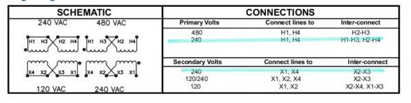
I have attached the wiring schematic, and have highlighted the way in which I believe I can achieve what I have explained. Wire the primary for the 240 configuration and the secondary also for the 240 configuration.
What do you guys think?
I was recently contracted to install a piece of equipment that needs to be protected by means of isolation. I plan to do this via a transformer. I have experience installing transformers for step up and step down applications, but have not installed one for an isolating scenario.
My question is, can I use a 240x480 - 120/240 step down transformer and wire it in such a way that is simply a 240 - 240 isolating transformer? So no step down occurs, it simply passes the same voltage through? I have never wired one like this.
I am looking at this transformer currently -
I have attached the wiring schematic, and have highlighted the way in which I believe I can achieve what I have explained. Wire the primary for the 240 configuration and the secondary also for the 240 configuration.
What do you guys think?
 I didn't know that! Oops.