You are using an out of date browser. It may not display this or other websites correctly.
You should upgrade or use an alternative browser.
You should upgrade or use an alternative browser.
Does my motor control book have an error?
- Thread starter zappy
- Start date

Tulsa Electrician
Senior Member
- Location
- Tulsa
- Occupation
- Electrician
Looks right to me.
Edit.
Looking at the bottom pic I see what you mean. I was looking at the first pic of the wiring diagram.
Edit.
Looking at the bottom pic I see what you mean. I was looking at the first pic of the wiring diagram.
Last edited:
Tulsa Electrician
Senior Member
- Location
- Tulsa
- Occupation
- Electrician
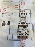
95 and 96 open on overload aka N/C
TwoBlocked
Senior Member
- Location
- Bradford County, PA
- Occupation
- Industrial Electrician
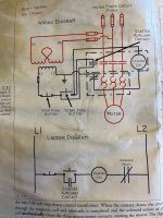
IMG_9845 is in error. The NC overload contacts must be used, terminals 95 & 96. If the NO overload contacts are used, the only way the motor could be started and run is if the overload was manually tripped. This would allow the motor to continue running if an overload condition should occur. The NO overload contacts (term 95 & 96) should only be used for indication.
TwoBlocked
Senior Member
- Location
- Bradford County, PA
- Occupation
- Industrial Electrician
This isn't a real complete schematic, but take a look at page 14: https://literature.rockwellautomation.com/idc/groups/literature/documents/td/193-td011_-en-p.pdf
LarryFine
Master Electrician Electric Contractor Richmond VA
- Location
- Henrico County, VA
- Occupation
- Electrical Contractor
This may be due to the difference between normal contact position when de-energized and when in use.
TwoBlocked
Senior Member
- Location
- Bradford County, PA
- Occupation
- Industrial Electrician
Another reference: https://www.se.com/us/en/faqs/FA107663/
- Location
- Illinois
- Occupation
- retired electrician
Terminals 95 and 96, the NC contact, are used on all IEC overload relays to open the power to the contactor coil.This may be due to the difference between normal contact position when de-energized and when in use.
Tulsa Electrician
Senior Member
- Location
- Tulsa
- Occupation
- Electrician
TwoBlocked
Senior Member
- Location
- Bradford County, PA
- Occupation
- Industrial Electrician
And this here might confuse it more. See if you can find where it is self-contradictory: https://studylib.net/doc/18040687/nema-and-iec-terminal-markings
Tulsa Electrician
Senior Member
- Location
- Tulsa
- Occupation
- Electrician
I'm not seeing what you see. Can you help meAnd this here might confuse it more. See if you can find where it is self-contradictory: https://studylib.net/doc/18040687/nema-and-iec-terminal-markings
TwoBlocked
Senior Member
- Location
- Bradford County, PA
- Occupation
- Industrial Electrician
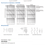
Top left is a table explaining the numbering system (Sure would like to see a complete, official one.) Bottom left is a diagram showing the contacts in a schematic. The table says 95 & 96 are NO, the diagram shows 95 & 96 as NC.I'm not seeing what you see. Can you help me
I used to do electrical design at a manufacturing plant and I notice stuff like that. Sooooo nice to be back in the field, even with a boss that is, er, simple-minded.
Tulsa Electrician
Senior Member
- Location
- Tulsa
- Occupation
- Electrician
Thanks, I will review again.Top left is a table explaining the numbering system (Sure would like to see a complete, official one.) Bottom left is a diagram showing the contacts in a schematic. The table says 95 & 96 are NO, the diagram shows 95 & 96 as NC.
I used to do electrical design at a manufacturing plant and I notice stuff like that. Sooooo nice to be back in the field, even with a boss that is, er, simple-minded.
Tulsa Electrician
Senior Member
- Location
- Tulsa
- Occupation
- Electrician
I enjoy learning new things.
I reviewed the table.
Could you give me an example how this would be applicable. I have used these for singling. Never for anything else.
I'm also aware these numbers can be used elsewhere other than the over load block N.O.
For other control items based on the symbols in table.
I would not think in this case it's applicable for the OP question. However I'm willing to learn.
Thank you in advance.
TwoBlocked
Senior Member
- Location
- Bradford County, PA
- Occupation
- Industrial Electrician
Gosh, sorry, I am trying to understand what you are asking. I enjoy a good conversation about electrical documentation. "I have used these for singling" Don't know what you mean. Can you give an example?I enjoy learning new things.
I reviewed the table.
Could you give me an example how this would be applicable. I have used these for singling. Never for anything else.
I'm also aware these numbers can be used elsewhere other than the over load block N.O.
For other control items based on the symbols in table.
I would not think in this case it's applicable for the OP question. However I'm willing to learn.
Thank you in advance.
I think the IEC numbering system is very applicable for the OPs question. Finding that table, although having a typo, gives me some info I'd been looking for for a while: First digit means what set the contacts belong to, with 9 reserved for timers and overloads. Second digit whether NC (1 & 2, 5 & 6) or NO (3 & 4, 7 & 8). With that info, you'd know that terminals 97 & 98 are for NO contacts on a timer or overload. In the OPs question, since this is on an OL block, it indicates that the second illustration is wrong.
I have been confused many, many times by what these IEC terminal numbers mean (along with other systems). I just drag out the documentation or my meter to figure it out when designing, or installing, or troubleshooting.
Still would LOOOVE to see a table of the terminal numbers, especially one that compares the different systems. I've looked, but never in the right place I guess. Maybe a new Topic?
TwoBlocked
Senior Member
- Location
- Bradford County, PA
- Occupation
- Industrial Electrician
This was helpful, but still not complete, and not directly from NEMA nor IEC: https://control.com/technical-articles/info-byte-whats-the-reason-behind-relay-terminal-numbering/
- Location
- San Francisco Bay Area, CA, USA
- Occupation
- Electrical Engineer
That's a quirk of the concept of "normal". In IEC world, the 95/96 contacts are in fact "normally" open, held closed by a spring loaded mechanism tied to the OL thermal element. If the thermal element releases the trip bar, the contacts RETURN to their "normal" state of being open.Top left is a table explaining the numbering system (Sure would like to see a complete, official one.) Bottom left is a diagram showing the contacts in a schematic. The table says 95 & 96 are NO, the diagram shows 95 & 96 as NC.
I used to do electrical design at a manufacturing plant and I notice stuff like that. Sooooo nice to be back in the field, even with a boss that is, er, simple-minded.
I grew up on NEMA, went to work for a German company (Klockner-Moeller), had to have my brain rewired on this issue (among others)... But being Germans, they had it ALL documented in excruciating detail, a process they referred to as "rationalization". They had VOLUMES of binders for us EEs to use if we had any questions, called "PR" manuals, standing for "Planen und Rationalisierung" (Planning and Rationalization in German). No detail was left unexplored and dissected to the Nth degree.
TwoBlocked
Senior Member
- Location
- Bradford County, PA
- Occupation
- Industrial Electrician
That does not explain why the table says one thing and the diagram shows another.That's a quirk of the concept of "normal". In IEC world, the 95/96 contacts are in fact "normally" open, held closed by a spring loaded mechanism tied to the OL thermal element. If the thermal element releases the trip bar, the contacts RETURN to their "normal" state of being open.
.....
Mr. Serious
Senior Member
- Location
- Oklahoma, USA
- Occupation
- Electrical Contractor
I looked. It's Sunday so I'm not supposed to do anything, but still it's frustrating to look and look and look without finding it, so I'm posting what I found so far, then I'm giving up.Still would LOOOVE to see a table of the terminal numbers.
I thought I had seen it before. But it turns out, the one I have seen before is for automotive wiring and the numbers have completely different meanings. Here is one such reference on the Internet Archive: Automotive component pin assignments.
As far as what we're actually looking for, these are what I found:
- There is a document from Siemens from June 2010 called "Terminal markings for IEC contactors and relays." This may be the best resource. It had a couple of accolades on a thread in a PLC forum thread from August, 2011. But I was only able to view the first page on Scribd and didn't find any other copy anywhere.
- There's the reference you already posted in replay #16 with the incomplete list.
- There's an ABB document, "Terminal Marking and Positioning." It is apparently section 8 of the ABB Low Voltage Products manuals, document number 1SBC100122C0202. I didn't see any list of terminal numbers, per se, but it does have explanations of terminal markings on all their low-voltage products, and it also lists standards that these markings come from: generally IEC 60445, IEC 60947-1 and EN 50005. Additionally,
- – IEC 60947-4-1, EN 60947-4-1 and EN 50012 for contactors and their auxiliary contacts,
- – IEC 60947-5-1 and EN 50011 for contactor relays,
- – IEC 60947-4-1 and EN 60047-4-1 for overload relays.
- An Eng-Tips forum thread Numbering of contactors and relays in wiring diagrams also lists some of the above standards as well as referencing IEEE-315. I didn't try looking that one up.