Distributed GenerationTransformer Bonding

Status
Not open for further replies.
So I am currently working on putting in a delta generator which is 480V and I need to step it up to 600V wye for my system.
My plan is to use a delta-wye step up transformer with the delta at the generator side and the wye on the bus side.

The bus side is an existing system with the neutral bonded at the main incoming service.
My question is in this case do I use a delta-wye instead of a delta-wye ground because if I grounded the wye high side then the system would have two neutral bonds which is against code?

Cheers
 

GoldDigger

Moderator
Staff member
Location
Placerville, CA, USA
Occupation
Retired PV System Designer
The secondary, high side, of the transformer is what is called a Separately Derived System (SDS) and so it has no conductors or ground reference in common with the primary side unless you provide one.
The NEC recognizes that an SDS is separate from the neutral/ground bond of the primary side.
It requires a ground neutral bond unless your intention is to operate and ungrounded system and you meet the additional requirement for that, namely a ground detector.

Sent from my XT1585 using Tapatalk
 

Smart $

Esteemed Member
Location
Ohio
You either use...
  • a 3-pole transfer switch with feed-through neutral and no additional neutral-ground bond, or
  • a 4-pole transfer switch with the neutral being one pole.
The first scenario is not an SDS. The latter is... so a system bonding jumper must be installed in the latter scenario
 
Thanks for your replies thus far!

I hope this attachment worked.
Just to clarify some things I added a picture that was drawn incredibly crudely by me and for that I apologize.
To avoid misinterpretation I added a A and bubble so we can reference the correct side of the transformer.

If I'm not mistaken side B is considered the separately derived system and from what GoldDigger said I need some sort of ground detecting on that side since there is no neutral.

On side A I am still a little confused.
I should not ground the WYE neutral on side A right? As this would mean the neutral is grounded in two spots.

All help is appreciated!

Cheers
 

Attachments

  • Rough Example.jpg
    Rough Example.jpg
    51.7 KB · Views: 3

Smart $

Esteemed Member
Location
Ohio
Where's your transfer switch?

Unless you have a self-synchronizing generator you need a transfer switch... unless you want a bunch of smoke. POCO may have an issue with direct connecting a generator to their system, too!

PS: Have you checked the availability of a 600V generator? I realize one may cost more, but does it cost more than a 480V generator plus step-up transformer. In either case, get a wye-configured generator.
 
Last edited:

iceworm

Curmudgeon still using printed IEEE Color Books
Location
North of the 65 parallel
Occupation
EE (Field - as little design as possible)
Ltl -
I'm guessing the project doesn't have any one-lines or any other drawings? That's okay, welcome to being the engineer of record.
Some context here will help. Are you discussing 25KW, 250KW, or 2.5MW of generation?

Minor disclaimer: I have no clue about the CEC rules concerning any of my comments.

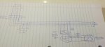
QUOTE=Lifetimelearner;1796651]Just to clarify some things I added a picture that was drawn incredibly crudely by me ....
I should not ground the WYE neutral on side A right? As this would mean the neutral is grounded in two spots. ...
[/QUOTE]
Fine picture. Good start on a three line diagram. . Couple of suggestions:
Add some circuit breakers to your three line.
Make up a one-line diagram Add all the data you have (or calculate, or determine), such as CBs, trip settings, xfm ratings, conductor sizes.​
If you draw this clear out, solutions to most of the questions will be apparent.

Transfer Switch: (building on S$ post)
You're showing the gen on the opposite end of the bus from the utility - so you can't use a common transfer switch. I'm guessing you will use the utility switchboard CB and the Gen xfm switchboard CB as the transfer switch. That's okay, but that makes it hard to interlock the transfer.

If you are doing this (using swb CBs as the transfer sw), unless you have some really odd stuff, the CBs are all 3pole. There won't be any switched neutral. So, the gen will not be an SDS. The gen xfm neutral will be connected to the swb neutral, the transformer ground will be connected to the swb ground. No bonding jumper at the gen xfm. Connection is 5Wire. If that is not the case, well, draw it out.

If I'm not mistaken side B is considered the separately derived system and from what GoldDigger said I need some sort of ground detecting on that side since there is no neutral.
GD is correct. However:
480 Delta generators are rare. There are few reasons to order one. I'm guessing you are stuck with used equipment from another project. Even when the plant system is ungrounded 480, the gen will often be 480Y and the Y-point left disconnected. First thing is to get the gen documentation and open the gen connection box. You could get lucky and there is a neutral :) or not :-( If there is a gen neutral - bond it. If not, then as GD says, ground detectors or you could corner ground the delta.

Ground detectors are pretty simple. Three 480V, transformered, incandescent pilots will work fine. Connect them Wye, with the Wye point connected to ground.

After you get these hammered out, the next concerns are:
Circuit breaker sizes, gen protection, GSU protection.
Paralleling - seamless return to utility, load testing for PMs
CB controls - prevent closing gen out-of-sync to live bus, prevent closing utility oos to live bus.

Sounds like a good project - keep us advised on how it works out.

iceworm
 
Thanks Smart $, GoldDigger and iceworm for the replies!

Just to clarify some things:
There are single lines and three lines (being designed by me) for the system but currently I am working out of office on another project and I'm not sure on my companies policy of sharing such drawings so I took to my art abilities.

The generator in question is an inverter based generator with its own controller for synchronizing and for protection elements (one of which is an Over Voltage Ground function).
The POCO is aware of the generator operating in parallel as this is the program we are focusing on.
The generator is used for CHP purposes and at this micro level of a 125kW with the heating loads required the 480V Delta generator was really the only option.
Circuit breakers and all such load calculations will be carried out and I realized after I drew the diagram I left out the CB's (that's on me).

The circuit breakers are located in between the main bus and the transformer as well as just after the generator.
Also for note there is a main control relay that determines how much power is being outputted by using CT's/PT's and a data connection to the generator controller.
Sorry for not posting more information to start, as iceworm, you're right the more information the better.

I guess my question still remains for the transformer on the A side, if I need to ground the neutral or does that represent a code violation?
Is Over Voltage Ground a replacement for the ground detection system?

Cheers
 

iceworm

Curmudgeon still using printed IEEE Color Books
Location
North of the 65 parallel
Occupation
EE (Field - as little design as possible)
You have a new gen ordered specifically for this project. New switchboards as well? Has the equipment been ordered? Has it arrived? Just curiosity questions. I'm not going to be able to help much. I really am clueless about a lot of what you are doing.

... The generator is used for CHP purposes and at this micro level of a 125kW with the heating loads required the 480V Delta generator was really the only option. ...
I don't know what "CHP purposes" are (is?) I don't know how heating loads could affect a gen connected directly to a xfm input. Unless these heating loads are connected to the gen output ahead of the GSU xfm. I am familiar with inverter output generators, but I didn't know they were stuck with delta outputs.

... I guess my question still remains for the transformer on the A side, if I need to ground the neutral or does that represent a code violation? ...

I'm guessing this didn't help:
Transfer Switch: (building on S$ post)
... If you are doing this (using swb CBs as the transfer sw), unless you have some really odd stuff, the CBs are all 3pole. There won't be any switched neutral. So, the gen will not be an SDS. The gen xfm neutral will be connected to the swb neutral, the transformer ground will be connected to the swb ground. No bonding jumper at the gen xfm. Connection is 5Wire. ...
Are you using SWB 3pole CB for the transfer? Cause if you are, the GSU xfm is not an SDS. The neutral is solid connected. The xfm connection is 5wire. If not, I'm no help - again.

... There are single lines and three lines (being designed by me) for the system ...
So what are the drawings showing? If you have drawing with a PE stamp on them (and they should be stamped), the questions your asking ae exactly what should be on them. But sometimes it isn't.

... Is Over Voltage Ground a replacement for the ground detection system? ...
Grab your generator book. What does that protective function measure?

So why did I take up your time with a bunch of worthless comment?
Don't know - probably shouldn't have. Didn't want you to think I was ignoring you. Sorry I can't help more.

ice
 

Smart $

Esteemed Member
Location
Ohio
...I guess my question still remains for the transformer on the A side, if I need to ground the neutral or does that represent a code violation?
Since you clarified the genset is paralleled with the utility (should have known with the topic header being Distributed Generation :ashamed1:), the neutral should already be grounded by way of the main bonding jumper at the service disconnecting means... solidly grounded and compliant. The other option is an Impedance Grounded Neutral System (that's Code speak for high resistance ground). There are only a few systems which are permitted to be ungrounded under 250.21(A)... and any of those require a ground detector.

Is Over Voltage Ground a replacement for the ground detection system?
Not familiar with that feature buzzword so I can't say for certain... but my general thought is that the feature would not be using a buzzword if there was an issue of compliancy.
 

Tony S

Senior Member
Will this generator supply local loads when the grid connection has failed? If it can things get interesting.

Running connected to the grid I’d go for impedance grounding of the transformer X0 terminal. You will need a neutral/ground current monitoring relay.
In islanded running (no grid connection) then a solid ground is needed for X0.

If I can find the name of the supplier I’ll post a link to an auto grounding switch.
 

iceworm

Curmudgeon still using printed IEEE Color Books
Location
North of the 65 parallel
Occupation
EE (Field - as little design as possible)
Will this generator supply local loads when the grid connection has failed? If it can things get interesting.

Running connected to the grid I’d go for impedance grounding of the transformer X0 terminal. You will need a neutral/ground current monitoring relay.
In islanded running (no grid connection) then a solid ground is needed for X0.

If I can find the name of the supplier I’ll post a link to an auto grounding switch.

Tony -
The Utility N-G bond will be on the customer side of the utility service disconnect. Actually that is not quite right. The Utility NG bond is not affected by the Utility Service disconnect. Utility disconnect open - Utility disconnect closed , doesn't matter. The SWB NG bond is still there.

I don't see the value of having an HRG on the GSU xfm.

ice
 

Tony S

Senior Member
If the CHP unit only runs when connected to the grid then a ∆∆ transformer would be better as only one N→G is in the system at the supply point.

Where the problem arises is if off grid operation is possible, some form of earth/ground reference is required. A ∆Y transformer is then required to give a neutral with earth/ground reference.
 

iceworm

Curmudgeon still using printed IEEE Color Books
Location
North of the 65 parallel
Occupation
EE (Field - as little design as possible)
If the CHP unit only runs when connected to the grid then a ∆∆ transformer would be better as only one N→G is in the system at the supply point.

Where the problem arises is if off grid operation is possible, some form of earth/ground reference is required. A ∆Y transformer is then required to give a neutral with earth/ground reference.

Yes, an N-G bond is required. And the one in the switchboard, likely right next to the utility disconnect, is still there.

If it isn't, that is another problem. A Delta-Delta GSU won't fix that.

Just curious, if a Delta-Delta GSU were to be used, and the system is on generation only, how does the D/D transformer supply any 277V loads?

Repeating: The N-G bond is in the swb. Any number of sources, be they transformers or generators, will be a 5wire connection to the swb.

ice
 
Status
Not open for further replies.
Top