Lastcall
New member
- Location
- New Orleans, LA
Hello all I am looking for help gaining understanding of NEC intent and requirements regarding bonding and grounding of residential services with and without ATS.
Without:
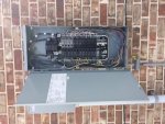
A split phase 120/240 3 wire overhead service from utility connecting to an outdoor service consisting of a 200A meter socket & 200A load center with main breaker (no other sub panels in structure). The load center panel has neutrals and grounds landed on he same bus not separated. The meter socket and panel are connected via 2” offset nipple with grounding bushings on both sides. The grounding electrode conductor for their service is unspliced attaching to two ground rods then passing through a lug on the neutral bus of the load center it continues unspliced through the 2” offset nipple attaching to one of the bonding bushings and finally terminating to the neutral lug in the meter can which is bonded to the can. This seems to be a standard accepted practice here and passes inspection. How is it that this does not create a parallel path for neutral current? See attached photo of load center.
Is this acceptable elsewhere what would you do differently?
I was asked to install a home standby generator on this service with a 3 pole ATS where the neutral is not switched. So I started to research the code because the gen had a neutral grounding jumper installed. I was easily able to determine this jumper should not be installed as the gen is not a SDS. However when I started to think about the ATS. It is a service disconnect model and has a bonding jumper installed. I am trying to determine what should be done to properly bond and ground the system. It seems the best thing to do would be run the GEC from the rods to the transfer switch and leave the MBJ in place. Then run a supply side bonding jumper from the ground bus in the ATS to a newly installed ground bus in the load center and from there to the grounding bushings on the nipple connecting the panel to the meter where it would stop. Then separate all the grounds From neutrals in the load center and place them on the newly installed ground bus which would be attached to the enclosure and isolated from the panel neutral bus. Is there a way to do this without separating the neutrals and grounds for the branch circuits in the load center or not ?
Any help much appreciated I have read till the words in 250 all look the same and my head hurts.
Thanks
Without:
A split phase 120/240 3 wire overhead service from utility connecting to an outdoor service consisting of a 200A meter socket & 200A load center with main breaker (no other sub panels in structure). The load center panel has neutrals and grounds landed on he same bus not separated. The meter socket and panel are connected via 2” offset nipple with grounding bushings on both sides. The grounding electrode conductor for their service is unspliced attaching to two ground rods then passing through a lug on the neutral bus of the load center it continues unspliced through the 2” offset nipple attaching to one of the bonding bushings and finally terminating to the neutral lug in the meter can which is bonded to the can. This seems to be a standard accepted practice here and passes inspection. How is it that this does not create a parallel path for neutral current? See attached photo of load center.
Is this acceptable elsewhere what would you do differently?
I was asked to install a home standby generator on this service with a 3 pole ATS where the neutral is not switched. So I started to research the code because the gen had a neutral grounding jumper installed. I was easily able to determine this jumper should not be installed as the gen is not a SDS. However when I started to think about the ATS. It is a service disconnect model and has a bonding jumper installed. I am trying to determine what should be done to properly bond and ground the system. It seems the best thing to do would be run the GEC from the rods to the transfer switch and leave the MBJ in place. Then run a supply side bonding jumper from the ground bus in the ATS to a newly installed ground bus in the load center and from there to the grounding bushings on the nipple connecting the panel to the meter where it would stop. Then separate all the grounds From neutrals in the load center and place them on the newly installed ground bus which would be attached to the enclosure and isolated from the panel neutral bus. Is there a way to do this without separating the neutrals and grounds for the branch circuits in the load center or not ?
Any help much appreciated I have read till the words in 250 all look the same and my head hurts.
Thanks