You are using an out of date browser. It may not display this or other websites correctly.
You should upgrade or use an alternative browser.
You should upgrade or use an alternative browser.
15 KVA ISOLATION TRANSFORMER GROUNDING
- Thread starter tld38
- Start date

- Status
- Not open for further replies.
- Location
- New Jersey
- Occupation
- Journeyman Electrician
What kind of files are you trying to upload? Maybe you can provide a link instead of the files. I think that your Shift key is stuck. ")
trying to send links to images
trying to send links to images
file:///C:/Users/tld38/Desktop/15%20KVA%20TRANSFORMER%20GROUNDING.pdf
trying to send links to images
file:///C:/Users/tld38/Desktop/15%20KVA%20TRANSFORMER.pdfWhat kind of files are you trying to upload? Maybe you can provide a link instead of the files. I think that your Shift key is stuck.
file:///C:/Users/tld38/Desktop/15%20KVA%20TRANSFORMER%20GROUNDING.pdf
- Location
- New Jersey
- Occupation
- Journeyman Electrician
Your links did not work. Are these personal files or can you point us to a place on the internet where we can view the information?
15 kva isolation transformer
15 kva isolation transformer
Hi Infinity, I was able to copy and paste on the links I posted then I was able to open them in new window. I did reply to moderator of this forum for any other suggestions as to be able to do this. as I stated in an earlier post, My file was 420kb, which is larger than the allowed 140kb on this forum. Thanks.
15 kva isolation transformer
Your links did not work. Are these personal files or can you point us to a place on the internet where we can view the information?
Hi Infinity, I was able to copy and paste on the links I posted then I was able to open them in new window. I did reply to moderator of this forum for any other suggestions as to be able to do this. as I stated in an earlier post, My file was 420kb, which is larger than the allowed 140kb on this forum. Thanks.
- Location
- Placerville, CA, USA
- Occupation
- Retired PV System Designer
Those links point directly to files on your computer's hard drive. Your browser knows to try to resolve a "file://" link directly on your computer instead of through the Internet. Others cannot do this!file:///C:/Users/tld38/Desktop/15%20KVA%20TRANSFORMER.pdf
file:///C:/Users/tld38/Desktop/15%20KVA%20TRANSFORMER%20GROUNDING.pdf
You apparently tried to use the "insert from URL" option instead of "insert from file". The latter requires the Forum to download and host the file, which it will not do for large files.
Sent from my XT1585 using Tapatalk
- Location
- New Jersey
- Occupation
- Journeyman Electrician
Just snap a photo of the file and post it that way.
.jpg")

- Location
- New Jersey
- Occupation
- Journeyman Electrician
I moved this here, please post comments in this thread instead of opening a new one.
15 kva isolation transformer grounding
15 kva isolation transformer grounding
I want to thank each and every person who has provided input on helping me find a solution to upload these images. I just need to figure out why the image is oriented correctly before upload, but then after upload it shows same image rotated 180 degrees. Thanks to all.
- Location
- New Jersey
- Occupation
- Journeyman Electrician

15 kva isolation transformer grounding
15 kva isolation transformer grounding
Thank You for your help infinity. i,m assuming that you have seen the other image of the transformer spec sheet that is actually going to be installed. I posted my questions on the spec sheet as to make it easier as the questions were long. I have been told that I may need some sort of phase monitor with lamps that would show the first fault if that were to take place so I could find the fault and repair before a second fault appeared. i,m not sure if that applies to this situation.
15 kva isolation transformer grounding
15 kva isolation transformer grounding
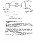
Hi to all. I,m posting my questions here as requested, as I have not received any responses to my questions posted in my sketch above. The one image shows the ACME spec sheet for the Xfmr that is actually being installed. It does not appear that the Xfmr is corner grounded. It appears that the Xfmr core is bonded to the case though. I'm assuming that the Xfmr case is grounded.
Question#1- Can i run a #10 equipment ground from the 277/480 Panel that is feeding the primary of the Xfmr, and bond the Xfmr case, and continue that ground to the 240 volt, 3 phase panel and Bond that panel as well? The 240 volt, 3 phase panel is for two- 3 pole 20 amp breakers that are feeding 2- VFD,s. No neutrals being used.
Question#2- Am I required to run a GEC from the Xfmr case to building steel? If so, can I run the GEC from the 240 volt, 3 phase panel to building steel instead?
Question#3- would I need to install phase monitor lamps that would alert me that 1 of the phases have grounded, which would then allow me to repair the first fault before a second fault occurred, as the the first fault would not trip the OCPD?
Question#4- Should I just bond the XO terminal of the Xfmr to the case instead of the above option, deriving the neutral and having a high leg at the 240 volt, 3 phase panel instead? This would seem to now require a bonding jumper and a supply side bonding jumper if I do it this way. I am hearing that this option may be safer.
Thanks to all. I want to insure that I am installing this correctly.
15 kva isolation transformer grounding
Hi to all. I,m posting my questions here as requested, as I have not received any responses to my questions posted in my sketch above. The one image shows the ACME spec sheet for the Xfmr that is actually being installed. It does not appear that the Xfmr is corner grounded. It appears that the Xfmr core is bonded to the case though. I'm assuming that the Xfmr case is grounded.
Question#1- Can i run a #10 equipment ground from the 277/480 Panel that is feeding the primary of the Xfmr, and bond the Xfmr case, and continue that ground to the 240 volt, 3 phase panel and Bond that panel as well? The 240 volt, 3 phase panel is for two- 3 pole 20 amp breakers that are feeding 2- VFD,s. No neutrals being used.
Question#2- Am I required to run a GEC from the Xfmr case to building steel? If so, can I run the GEC from the 240 volt, 3 phase panel to building steel instead?
Question#3- would I need to install phase monitor lamps that would alert me that 1 of the phases have grounded, which would then allow me to repair the first fault before a second fault occurred, as the the first fault would not trip the OCPD?
Question#4- Should I just bond the XO terminal of the Xfmr to the case instead of the above option, deriving the neutral and having a high leg at the 240 volt, 3 phase panel instead? This would seem to now require a bonding jumper and a supply side bonding jumper if I do it this way. I am hearing that this option may be safer.
Thanks to all. I want to insure that I am installing this correctly.
Last edited:
15 kva isolation transformer grounding
15 kva isolation transformer grounding
I Was mistaken on last post. There is no XO terminal as this not a delta/wye Xfmr. According to the ACME Xfmr diagram, to establish the neutral, I would run a 4th wire from
(X1,X4 Or X2, X4)? And this would create a high leg at the 240 volt/3 phase panel on B phase?
15 kva isolation transformer grounding
15 kva isolation transformer grounding
uested, as I have not received any responses to my questions posted in my sketch above. The one image shows the ACME spec sheet for the Xfmr that is actually being installed. It does not appear that the Xfmr is corner grounded. It appears that the Xfmr core is bonded to the case though. I'm assuming that the Xfmr case is grounded.
Question#1- Can i run a #10 equipment ground from the 277/480 Panel that is feeding the primary of the Xfmr, and bond the Xfmr case, and continue that ground to the 240 volt, 3 phase panel and Bond that panel as well? The 240 volt, 3 phase panel is for two- 3 pole 20 amp breakers that are feeding 2- VFD,s. No neutrals being used.
Question#2- Am I required to run a GEC from the Xfmr case to building steel? If so, can I run the GEC from the 240 volt, 3 phase panel to building steel instead?
Question#3- would I need to install phase monitor lamps that would alert me that 1 of the phases have grounded, which would then allow me to repair the first fault before a second fault occurred, as the the first fault would not trip the OCPD?
Question#4- Should I just bond the XO terminal of the Xfmr to the case instead of the above option, deriving the neutral and having a high leg at the 240 volt, 3 phase panel instead? This would seem to now require a bonding jumper and a supply side bonding jumper if I do it this way. I am hearing that this option may be safer.
Thanks to all. I want to insure that I am installing this correctly.
Last edited by tld38; Today at 01:23 AM.
15 kva isolation transformer grounding
Just snap a photo of the file and post it that way.
uested, as I have not received any responses to my questions posted in my sketch above. The one image shows the ACME spec sheet for the Xfmr that is actually being installed. It does not appear that the Xfmr is corner grounded. It appears that the Xfmr core is bonded to the case though. I'm assuming that the Xfmr case is grounded.
Question#1- Can i run a #10 equipment ground from the 277/480 Panel that is feeding the primary of the Xfmr, and bond the Xfmr case, and continue that ground to the 240 volt, 3 phase panel and Bond that panel as well? The 240 volt, 3 phase panel is for two- 3 pole 20 amp breakers that are feeding 2- VFD,s. No neutrals being used.
Question#2- Am I required to run a GEC from the Xfmr case to building steel? If so, can I run the GEC from the 240 volt, 3 phase panel to building steel instead?
Question#3- would I need to install phase monitor lamps that would alert me that 1 of the phases have grounded, which would then allow me to repair the first fault before a second fault occurred, as the the first fault would not trip the OCPD?
Question#4- Should I just bond the XO terminal of the Xfmr to the case instead of the above option, deriving the neutral and having a high leg at the 240 volt, 3 phase panel instead? This would seem to now require a bonding jumper and a supply side bonding jumper if I do it this way. I am hearing that this option may be safer.
Thanks to all. I want to insure that I am installing this correctly.
Last edited by tld38; Today at 01:23 AM.
What kind of files are you trying to upload? Maybe you can provide a link instead of the files. I think that your Shift key is stuck.
I Was mistaken on last post. There is no XO terminal as this not a delta/wye Xfmr. According to the ACME Xfmr diagram, to establish the neutral, I would run a 4th wire from
(X1,X4 Or X2, X4)? And this would create a high leg at the 240 volt/3 phase panel on B phase?
- Location
- New Jersey
- Occupation
- Journeyman Electrician
uested, as I have not received any responses to my questions posted in my sketch above. The one image shows the ACME spec sheet for the Xfmr that is actually being installed. It does not appear that the Xfmr is corner grounded. It appears that the Xfmr core is bonded to the case though. I'm assuming that the Xfmr case is grounded.
Question#1- Can i run a #10 equipment ground from the 277/480 Panel that is feeding the primary of the Xfmr, and bond the Xfmr case, and continue that ground to the 240 volt, 3 phase panel and Bond that panel as well? The 240 volt, 3 phase panel is for two- 3 pole 20 amp breakers that are feeding 2- VFD,s. No neutrals being used.
Question#2- Am I required to run a GEC from the Xfmr case to building steel? If so, can I run the GEC from the 240 volt, 3 phase panel to building steel instead?
Question#3- would I need to install phase monitor lamps that would alert me that 1 of the phases have grounded, which would then allow me to repair the first fault before a second fault occurred, as the the first fault would not trip the OCPD?
Question#4- Should I just bond the XO terminal of the Xfmr to the case instead of the above option, deriving the neutral and having a high leg at the 240 volt, 3 phase panel instead? This would seem to now require a bonding jumper and a supply side bonding jumper if I do it this way. I am hearing that this option may be safer.
Thanks to all. I want to insure that I am installing this correctly.
Last edited by tld38; Today at 01:23 AM.
OK let's start with terminology for future reference. On the primary you have an EGC (Equipment Grounding Conductor) run with the circuit conductors. On the secondary you have a SSBJ (Supply Side Bonding Jumper) run with the derived or secondary conductors. From the midpoint of one winding on the secondary you have a GEC (Grounding Electrode Conductor) run to the GES (Grounding Electrode System), in this case building steel, and a SBJ (system bonding jumper) which connects the secondary midpoint to the SSBJ and EGC.
1) Yes, if the EGC and SSBJ are the proper size.
2) At 240/120 volts you have a midpoint on the secondary so you are required to connect a GEC to the GES. {250.20(B)(1)}.
3) Not applicable because the secondary is required to be grounded, see #2.
15 kva isolation transformer grounding
15 kva isolation transformer grounding
Infinity, thank you for your feedback. if you look at the 1st page of the thread, you will see the ACME drawing for the Xfmr I am going to install. It looks like the core is grounded to the case. I want to run the EGC from the 277/480 volt panel feeding the primary and bond to the Xfmr case. I will then run 3 hots with a SSBJ from the secondary to the 240 volt 3 phase panel. I will bond the SSBJ to the Xfmr case and the 240 volt 3 phase panel as well. I will bond the 240 volt 3 phase panel with the factory bonding screw or strap that is provided from the factory as well. I will then run a GEC from the Xfmr case to building steel. I do not need to derive a neutral from the separately derived system as there is no neutrals needed at the 240 volt 3 phase panel.
Am I on the right path here? Thanks
MTW
Senior Member
- Location
- SE Michigan
You still need to connect S4 to the case (that is the supply side bonding jumper). This allows for fault current to return to the secondary coil.
Your transformer output is a center tapped delta with a hi leg. Since your using it to power two VFD's, you might want to check the VFD manuals. Many of them are restricted from being powered from a hi leg delta. They often require a wye input or to disconnect the MOV input protection.
Your transformer output is a center tapped delta with a hi leg. Since your using it to power two VFD's, you might want to check the VFD manuals. Many of them are restricted from being powered from a hi leg delta. They often require a wye input or to disconnect the MOV input protection.
- Status
- Not open for further replies.