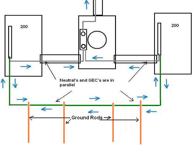
Dual panel Service 200A panels fed from a single 320 meter, each panel connected to the GEC via taps bonded to neutrals in each panel. This creates a low impedance path between the neutrals of each panel. Imbalance current at the neutral has two paths to the meter. One via the panel neutral, and the other along the GEC taps to the other panel, and along that panel's neutral to the meter. It seems to me, given the low impedance path between neutrals (along the GEC taps) that these wires will carry more than a negligible balance of current. Am I understanding this correctly? Is there any concern about this current flowing along the taps on a regular basis? Could a ground fault flowing on top of an existing imbalance exceed the ampacity of the GEC taps?
You are using an out of date browser. It may not display this or other websites correctly.
You should upgrade or use an alternative browser.
You should upgrade or use an alternative browser.
320/400 Dual Panel Service Bonded at the Panels - GEC Current
- Thread starter JPinVA
- Start date

- Status
- Not open for further replies.
- Location
- New Jersey
- Occupation
- Journeyman Electrician
It's normal to have some current flowing on the GEC or when used a metal raceway between pieces of equipment that have their neutrals bonded to their respective enclosures. In this case you have separate neutrals from each panel to the meter and bonding jumpers from the GEC to each panel. The bonding jumpers end up connecting to two neutrals in parallel. All of this is normal.
Welcome to the Forum.")
Welcome to the Forum.
kwired
Electron manager
- Location
- NE Nebraska
Current will take all available paths. Metal raceways or structure components between meter and each service disconnect are also in parallel to the grounded conductor in such an installation. NEC doesn't consider this to be objectionable current though. If you still want to avoid such parallel paths you are allowed to connect the GEC to any point up to the end of service drop or lateral - though some POCO's may have rules on what you can or can't do in meter sockets.
though some POCO's may have rules on what you can or can't do in meter sockets.
Dominion Virginia Power does not allow GEC connections in meter or CT cabinets.
I'm just trying to get my mind around what's really going through the GEC taps. We have 2/0 neutrals running back to the meter, but #2 at the taps. As both paths are low impedance, I have to wonder if 2/0 is needed to handle the phase imbalance along the neutral to the meter why is #2 good enough for current on the tap?
kwired
Electron manager
- Location
- NE Nebraska
Dominion Virginia Power does not allow GEC connections in meter or CT cabinets.
I'm just trying to get my mind around what's really going through the GEC taps. We have 2/0 neutrals running back to the meter, but #2 at the taps. As both paths are low impedance, I have to wonder if 2/0 is needed to handle the phase imbalance along the neutral to the meter why is #2 good enough for current on the tap?
Again NEC doesn't consider this as objectionable current. Reality is your 2/0 neutral likely never sees anywhere it's ampacity either on most dwellings supplied by 120/240. Neutral on 120/208 three wire will see higher current levels, probably still fairly minimal on most 200 amp feed for a dwelling though.
jumper
Senior Member
- Location
- 3 Hr 2 Min from Winged Horses
Dominion Virginia Power does not allow GEC connections in meter or CT cabinets.
I'm just trying to get my mind around what's really going through the GEC taps. We have 2/0 neutrals running back to the meter, but #2 at the taps. As both paths are low impedance, I have to wonder if 2/0 is needed to handle the phase imbalance along the neutral to the meter why is #2 good enough for current on the tap?
Yeah, Dominion never lets one use their stuff for the GEC.
Basically, we ignore this “objectionable current” at the service because the NEC allows it.
We pretend that the neutral is carrying all the imbalance....instead of the parallel taps also carrying some.
kwired
Electron manager
- Location
- NE Nebraska
IF you happened to have metallic water system in the area and per NEC used the water pipes as electrodes, you have all sorts of parallel currents flowing on that water system in any given neighborhood.
NEC doesn't consider that to be objectionable current. Can create shock hazards when a "normal" neutral path becomes compromised though.
NEC doesn't consider that to be objectionable current. Can create shock hazards when a "normal" neutral path becomes compromised though.
- Location
- New Jersey
- Occupation
- Journeyman Electrician
We have 2/0 neutrals running back to the meter, but #2 at the taps. As both paths are low impedance, I have to wonder if 2/0 is needed to handle the phase imbalance along the neutral to the meter why is #2 good enough for current on the tap?
Are both paths equal? Isn't the GEC is connected to the electrode and there is no connection to the electrode in the meter?
jumper
Senior Member
- Location
- 3 Hr 2 Min from Winged Horses
JPin,
Can you draw out exactly what you have? Or wish to discuss?
Simple diagram?
Can you draw out exactly what you have? Or wish to discuss?
Simple diagram?
JPin,
Can you draw out exactly what you have? Or wish to discuss?
Simple diagram?

Above image is close enough. Any imbalance arriving on either neutral will not only flow along the neutral back to source, but will flow thorough the taps to the GEC, and over to the other panel's neutral and back to source. I'm NOT talking about current flowing down to the grounding electrodes and along ground back to transformer (the proverbial 25 ohm path). I'm talking about the path between the neutral bar in each panel, along the GEC taps and GEC.
Of particular interest is the sizing of the taps are a couple of notches smaller than the neutral feed, but will be carrying similar levels of current. In the example above, it is compounded even more by the different feeders to each panel. We have an 8 AWG tap on the first panel (sized based on the neutral feeder to that panel), but it may be carrying current imbalance off of the neutral from panel 2.
My initial query is whether anyone else sees this as an issue. I know it's code compliant. So I don't have an issue in terms of code. I presume when the code was written, this situation was assessed and deemed "OK". I'm just looking to see some of the logic behind the decision.
Edit: One other observation. I believe the phase delta add/subtract will be opposite along the GEC link. That is, same phase current (arriving at each neutral) will have a subtracting effect on the current observed along the GEC link. Opposite phase current will have an additive effect. It all comes out in the wash at the meter as the current heads for home. But one thing to note is you can have zero from meter to transformer and have substantial current along the GEC between the panel neutrals.
Last edited:
jumper
Senior Member
- Location
- 3 Hr 2 Min from Winged Horses
Yeah, I thought you were referring to the above.
OK, I've taken the figure and added some imbalance current. Don't get too caught up on the chosen numbers. It's the concept I'm illustrating. I'm assuming the GEC path between neutrals is equal in impedance to the path from each neutral to gutter. In this example, I've illustrated 90A of imbalance at panel 2, and 60A of imbalance at panel 1. The imbalance at each panel are split phase wrt to each other. They cancel at the gutter, leaving 30A net back to transformer. Look at the GEC current. It's the most of all. Yet, the panel 1 tap is the smallest wire of them all. The 8 AWG is based on the panel 1 feeder. But in this configuration, panel 2, a much larger feeder, can tax that wire.

jumper
Senior Member
- Location
- 3 Hr 2 Min from Winged Horses
I may not be completely understanding the OP's installation but, the illustration below is the way I envision it and even though it is legal it is a bad design.
Roger
Either set up illustrates the problem with our services and noodle current, we say no “objectionable current” and then waffle and say well, if it is the service, okay...:slaphead:
Kinda why I said we pretend and ignore this particular problem, what else can we do?
LarryFine
Master Electrician Electric Contractor Richmond VA
- Location
- Henrico County, VA
- Occupation
- Electrical Contractor
In the "olden days" before plastic water piping, it was not uncommon for a poor service neutral to remain undiscovered . . . until a water meter was removed.
jaggedben
Senior Member
- Location
- Northern California
- Occupation
- Solar and Energy Storage Installer
... We have 2/0 neutrals running back to the meter, but #2 at the taps. As both paths are low impedance, I have to wonder if 2/0 is needed to handle the phase imbalance along the neutral to the meter why is #2 good enough for current on the tap?
Since there are two paths the #2 would only have to handle half of the maximum current possible. I kinda see your point if I study the ampacity tables, but they don't have to both be sized for the maximum load. Also it doesn't matter too much if any insulation on the GECs melts.
The copper isn't going to melt. A bare GEC probably has no issue carrying the current, although I suppose it might get hot to the touch in an extreme situation.Also keep in mind that the metal parts between the two disconnects are yet another pathway that can take some burden off the neutral and GEC.
Of particular interest is the sizing of the taps are a couple of notches smaller than the neutral feed, but will be carrying similar levels of current. In the example above, it is compounded even more by the different feeders to each panel. We have an 8 AWG tap on the first panel (sized based on the neutral feeder to that panel), but it may be carrying current imbalance off of the neutral from panel 2. My initial query is whether anyone else sees this as an issue. I know it's code compliant. So I don't have an issue in terms of code. I presume when the code was written, this situation was assessed and deemed "OK". I'm just looking to see some of the logic behind the decision.
I see the point you are raising about different sizes and I think it's in an interesting issue. I'm doubtful of it being a real world issue unless the two different sizes are seriously out of whack, say the max 3/0 on one tap and 8awg on the other. Maybe the reason the code hasn't been changed is that tolerances are high enough that in the real world this has never been known to start a fire. Or at least, not often enough to catch the attention of anyone who writes the code.
...Edit: One other observation. I believe the phase delta add/subtract will be opposite along the GEC link. That is, same phase current (arriving at each neutral) will have a subtracting effect on the current observed along the GEC link. Opposite phase current will have an additive effect. It all comes out in the wash at the meter as the current heads for home. But one thing to note is you can have zero from meter to transformer and have substantial current along the GEC between the panel neutrals.
OK, I've taken the figure and added some imbalance current. ...
The last picture is sort of useless without a red wire shown, but I get what you are trying to say. However, I'd point out the worst case scenario is simply maximum unbalanced current on one wire of one meter (the larger if they are different) and zero current on the other meter. The balancing of current on different phases between the two different meters can't make it any worse than that.
Adamjamma
Senior Member
- Location
- Jamaica and london
Wouldn’t this be better if you ran it through a trough, running a grounding bar in the trough, then feeding both panels with neutral and grounds separated? Or even a 320 breaker or fused disconnect to make ground spot before splitting to the 200 amp panels? Remember, before yelling, am a student, not experienced in these big loadsI may not be completely understanding the OP's installation but, the illustration below is the way I envision it and even though it is legal it is a bad design.
Roger
kwired
Electron manager
- Location
- NE Nebraska
250.24(B) still would require bonding the grounded conductor within the enclosure for each service disconnecting means, which would still create the parallel paths you are trying to avoid.Wouldn’t this be better if you ran it through a trough, running a grounding bar in the trough, then feeding both panels with neutral and grounds separated? Or even a 320 breaker or fused disconnect to make ground spot before splitting to the 200 amp panels? Remember, before yelling, am a student, not experienced in these big loads
250.24(B) still would require bonding the grounded conductor within the enclosure for each service disconnecting means, which would still create the parallel paths you are trying to avoid.
Not necessarily. The neutral/ground of each enclosure will not "itself" create a low impedance parallel path between enclosures. If there is no other low impedance path between enclosures, and the GEC taps are removed because the GEC is now connected in the trough, the only low impedance path is the neutral feeder between each panel and the trough. The trough becomes a "true" single point bond, trough connection notwithstanding.
jumper
Senior Member
- Location
- 3 Hr 2 Min from Winged Horses
Not necessarily. The neutral/ground of each enclosure will not "itself" create a low impedance parallel path between enclosures. If there is no other low impedance path between enclosures, and the GEC taps are removed because the GEC is now connected in the trough, the only low impedance path is the neutral feeder between each panel and the trough. The trough becomes a "true" single point bond, trough connection notwithstanding.
Are you referring to the pic you posted?
If GEC was landed in the trough, taps are gone.
Assuming metal trough and metal nipples, parallel neutral path. Use PVC, no parallel path.
- Status
- Not open for further replies.