mbrooke
Batteries Included
- Location
- United States
- Occupation
- Technician
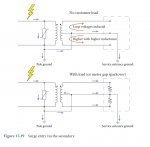
Lightning, by a number of different mechanisms, results in a large charge, with a very fast rise time, propagating down conductors at high speed. When the "pulse" reaches an impedance change (the end of a conductor at a "no load" location), the pulse reflects off the impedance change and travels back on the same conductor. The reflected pulse ADDS to the arriving (not yet reflected) pulse, effectively doubling the strength of the pulse.
Connected premises load, depending upon what it actually is, will tend to be a much lower impedance-to-ground than the open at the end of a conductor.
. . . having all L-L connected loads will equal to not having any load connected?
With respect to the reflection of the lightning caused surge, I was first introduced to the idea while working for a PoCo in eastern Nebraska. As rural electrification built out, and in the next few decades, engineers noted a pattern of lightning damage that occurred at the end of primary spurs that would dead end (such as at a farmstead), or that occurred when aerial primary transitioned to underground cable (not where it entered the ground, but literally the splice). The pulse energy under-the-curve was doubling at the physical point of reflection off the impedance change.
Impedance as in ohms, or surge impedance loading?
DC models of the things around, and connected to, the conductor bearing the lightning surge will have little use. The faster the rise time, the greater the high frequency components of the surge. The actual circuit characteristics of the things that comprise the assembly that includes the conductor will be complex, to say the least, as experienced by the high frequency components of the pulse. Add to that the effects of the Earth itself in relationship to the event that lead to the lightning discharge.
My point: making a definitive statement will require a lot more detail than the line diagrams in your OP, and will certainly be beyond me.
How does a standing wave occur in an antenna? It is a single wire that simply ends on one end and is connected through an oscillator to Earth on the other end.
At an open circuit end of a transmission line (which is how we need to model the distributed inductance and capacitance), the current must be zero unless a bulk capacitor is connected to the line (in which case it is not actually open). The only way current can be zero is if there is an equal and in-phase reflection moving in the opposite direction. So current is zero but voltage doubles. And after propagation delay the oscillator gets hit by the return wave. The phase of that return wave at the oscillator will depend on the length of the line times two.Good point.
But honestly I'm murky on the theory.
At an open circuit end of a transmission line (which is how we need to model the distributed inductance and capacitance), the current must be zero unless a bulk capacitor is connected to the line (in which case it is not actually open). The only way current can be zero is if there is an equal and in-phase reflection moving in the opposite direction. So current is zero but voltage doubles. And after propagation delay the oscillator gets hit by the return wave. The phase of that return wave at the oscillator will depend on the length of the line times two.
Among other things, that means that if you have a line 1/4 wave long and open at the end it looks like a short circuit at the generator. Ouch.
Amateur Radio operators (at least VHF and above) are very familiar with this.
")
At an open circuit end of a transmission line (which is how we need to model the distributed inductance and capacitance), the current must be zero unless a bulk capacitor is connected to the line (in which case it is not actually open). The only way current can be zero is if there is an equal and in-phase reflection moving in the opposite direction. So current is zero but voltage doubles. And after propagation delay the oscillator gets hit by the return wave. The phase of that return wave at the oscillator will depend on the length of the line times two.
Among other things, that means that if you have a line 1/4 wave long and open at the end it looks like a short circuit at the generator. Ouch.
Amateur Radio operators (at least VHF and above) are very familiar with this.
Unlike an oscillator / antenna that are tuned on a fundamental frequency, lightning, with its extremely fast rise times presents a messy collection of frequencies of varying magnitudes. That is, mega different frequencies of mega different magnitudes that, when taken together, is probably as unique as a snowflake.In other words lighting just behaves like mega hertz AC electricity?
Quite possibly, depending on the length and configuration of the neutral wire back to the POCO neutral.And that means a 25 ohm ground rod is better at transferring lighting to ground then the MGN despite the MGN having a lower DC resistance to earth?
How does a standing wave occur in an antenna? It is a single wire that simply ends on one end and is connected through an oscillator to Earth on the other end.
Good point.
But honestly I'm murky on the theory.
Amateur Radio operators (at least VHF and above) are very familiar with this.
i once had a job running pipe & grounding a ham radio on a mountain top, needing guidance i finally found a 780 guy
i installed as advised.....but i'll be the 1st to say i had no clue as to the theory behind it :happysad:~RJ~
OK, I'll bite. What, or who, is a "780 guy"?