Building services/feeders - grounding and bonding question

Status
Not open for further replies.

steve66

Senior Member
Location
Illinois
Occupation
Engineer
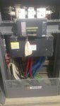
A client has a 4160 volt service. That supplies 4 or 5 transformers scattered around the building. Each transformer supplies 208 volts to separate main switchboards inside the building, and each switchboard has a 2000 amp main breaker.

I have a couple of questions regarding the feeders between each transformer and its main switchboard.

1. Can these be 4 wire feeders? As in 3 hot wires and a grounded service conductor? This is how they would be installed if they were service conductors. (i.e. - If the power company owned the transformers, and the services were 208 volts.) However, I believe I've heard this may not be allowed for customers owned transformers.

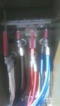
2. Can these be 5 wire feeders? Then we would have 3 hot wires, a neutral, and a ground from each transformer to each switchboard.

3. If they are 5 wire feeders, where should the bonding between neutral and ground occur? In the transformer, or in the switchboard? Both the transformer and the switchboard are shipped with a bonding jumper installed between the neutral connection and the ground connection. I assume one of these would have to be removed.
 

iwire

Moderator
Staff member
Location
Massachusetts
It does not sound like a feeder it sounds like transformer secondary conductors and should be wired just like any SDS that was inside the building.

The bonding can be at the transformer or at the switchboard, or both under exception 2 of 250.30(A)(1)
 

Smart $

Esteemed Member
Location
Ohio
...both under exception 2 of 250.30(A)(1)
I realize the exception is still in Code, but it is rendered moot if installation is under 2011 or 2014, both of which require a supply-side bonding jumper (SSBJ) [250.30(A)(2)]. An SBJ at both locations along with an SSBJ between them would create a parallel path for grounded conductor current.
 

iwire

Moderator
Staff member
Location
Massachusetts
I realize the exception is still in Code, but it is rendered moot if installation is under 2011 or 2014, both of which require a supply-side bonding jumper (SSBJ) [250.30(A)(2)]. An SBJ at both locations along with an SSBJ between them would create a parallel path for grounded conductor current.


The dirt does not count so I am missing the second path assuming PVC conduits.
 

kwired

Electron manager
Location
NE Nebraska
If the 4160 is customer equipment and not utility Co. equipment then the 4160 is feeders and your transformers are separately derived systems. Same basic rules apply as if they were 480 x 208/120 transformers.

If the 4160 is POCO owned/operated, then the secondaries of those transformers are service conductors - be careful you don't have violations on number of services permitted at the facility.
 

Smart $

Esteemed Member
Location
Ohio
The only reason I can think of to keep 250.30(A)(1) Exception No. 2 in the Code is to allow removal of the SSBJ of 250.30(A)(2) under 250.6(B)... but that just don't seem right either.
 

Smart $

Esteemed Member
Location
Ohio
Again, dirt does not count so I am still not seeing the second path for neutral current.
Consider "ground" in that post as non-current-carrying metal.

That wouldn't matter anyway. The parallel path is SBJ1-SSBJ-SBJ2.
 

iwire

Moderator
Staff member
Location
Massachusetts
The only reason I can think of to keep 250.30(A)(1) Exception No. 2 in the Code is to allow removal of the SSBJ of 250.30(A)(2) under 250.6(B)... but that just don't seem right either.

Well it is kind of interesting as there is no purpose for a supply side bonding jumper when the bonding is done at both ends and a grounded conductor is installed.

I would likely not install the SSBJ if I was bonding at both ends and see how the inspector feels. :D
 

Smart $

Esteemed Member
Location
Ohio
Well it is kind of interesting as there is no purpose for a supply side bonding jumper when the bonding is done at both ends and a grounded conductor is installed.

I would likely not install the SSBJ if I was bonding at both ends and see how the inspector feels. :D
I agree.

But I see it as a Code conflict in that an SSBJ is required, while a second SBJ is only permitted under exception. If I were the inspector, I might let it slide the first time, but I'd be sure to make that contractor aware of what I just mentioned and add that I will not let it slide again... but then again, I am not an inspector :happyno:.
 

iwire

Moderator
Staff member
Location
Massachusetts
.. but then again, I am not an inspector

AwesomeSmiley.gif


:p
 

steve66

Senior Member
Location
Illinois
Occupation
Engineer
So, please correct me if I'm wrong, but it sounds like the conclusion is that a 5 wire feeder is required.

Consider "ground" in that post as non-current-carrying metal.

That wouldn't matter anyway. The parallel path is SBJ1-SSBJ-SBJ2.

So in layman's terms, that would put the white wires in parallel with the green ones, correct? (assuming standard color coding.) So one SBJ jumper or the other would need to be removed.

Here are a couple of photos, just to clarify.


IMAG4651.jpg
IMAG4647.jpg


IMAG4645.jpg

In the photo of the switchboard, it appears the SBJ is the vertical piece of bus in the front of the switchboard, shown in the lower left corner of the photo.

And in the photo of the transformer, the SBJ would be the strap between X0 and the enclosure.

So one of these should be removed?

Edit: Enlarged the photos a little.
 

Attachments

  • IMAG4651.jpg
    IMAG4651.jpg
    19.8 KB · Views: 0
  • IMAG4645.jpg
    IMAG4645.jpg
    19.4 KB · Views: 0
Last edited:

Smart $

Esteemed Member
Location
Ohio
5-wire if you run an SSBJ, or 4-wire if you do as iwire suggests (without SSBJ). I'd go with 5-wire, as it would not give any reason for rejection by inspector.

And, yes, remove one of the bonds if using 5-wire.
 

steve66

Senior Member
Location
Illinois
Occupation
Engineer
Does the transformer have provisions to bond/isolate the frame from the X0 terminal?

To be honest, I'm not sure. In the second photo I posted, you can see a solid copper strap that goes from the X0 terminal to the enclosure, and two bolts that appear to connect it to the enclosure. I assume one could remove the two bolts and bend the strap out away from the enclosure to isolate the X0 terminal.

To actually remove the strap, it looks like one would have to remove the X0 lug. I'm not sure how that's done. (As an engineer, I don't ever get the chance to take a wrench and start turning bolts in these things to see what happens. So what may appear obvious to you contractors isn't always so obvious to the engineering crowd.)

The strap in the switchboard seems much more straightforward, and easier to remove. I'm leaning toward telling the contractor to remove that one. And it seems reasonable to have the main jumper in the transformer.

Here is a photo that should be better:

New Photo medium.jpg
 
Last edited:
Status
Not open for further replies.
Top