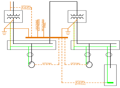
Thanks, it makes more sense now. I did not know that in NEC, the connection of electrode of transformer 1 to the electrode of transformer 2 was optional.
It's not optional. There are basically two frames of thought for your situation: 1) each transformer has a GES as a separate structure, or 2) the transformers electrodes are part of the building GES.
In case 1, the building is required to have its own GES. Nevertheless, all the separate GES's would be connected together through required, non-GEC grounding conductors.
Case 2 requires the electrodes be bonded together to form the building GES and appears to be the frame of thought in your situation.
Yes please remove the parallel paths in your diagram that you have mentioned.
I don't know for certain what I was thinking when I wrote that. There's obviously parallel ground
ing conductor paths, and I think at the time that bled over into parallel ground
ed paths... quite errantly on my part. There likely will be some grounded [neutral] conductor current on the grounding system, but an inadvertent result and unavoidable consequence of compliant grounding.