Adding Z of transformers and wiring and X/R ratios

Status
Not open for further replies.

tersh

Senior Member
Location
new york
Can you just add the impedances of transformers and wiring?

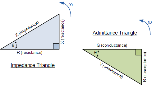
Is it not adding Z1 + Z2 is based on the assumption that X/R is the same for both?

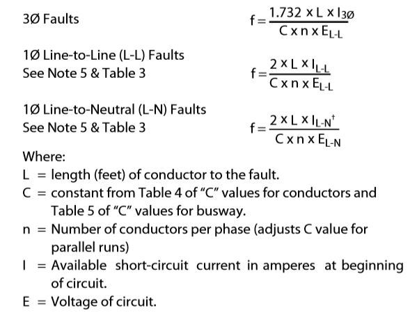
I'm asking because the NEC formulas for getting the bolted short circuit current is by getting the impedances of both and just adding them, but what if they don't have the same X/R ratio?

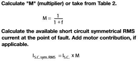
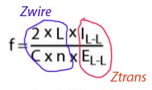
See https://forums.mikeholt.com/showthread.php?t=197174&page=2 for detailed calculations proving the Point to Point Fault Calculation method is simply adding the Z1 + Z2 then dividing the voltage by the total Z to get the bolted short circuit current. Even if you are not familiar with short circuit current computations. Just let me know in general about adding impedances of transformers and wiring with different X/R ratios.

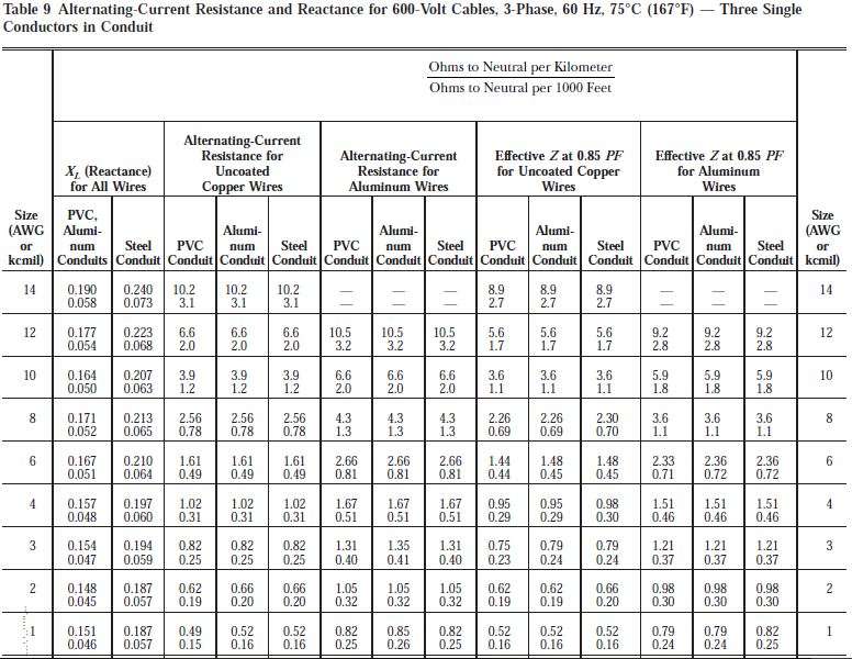
Also what are the common X/R of transformers and especially wiring.. are they close so you can just add them? Thanks.
 
Last edited:

Julius Right

Senior Member
Occupation
Electrical Engineer Power Station Physical Design Retired
If you know how to work with complex numbers it is very simply.
For the transformer Zxfr=Rxfr+iXxfr and for cable Zcb=Rcb+iXcb
Never the less the supply system it is 3 phases the 208V system it is a single phase system.
EAB+ECA/2+VBN=0 then VBN=-(EAB+ECA/2)[as you said VBN=207.8461 V.]
From the name plate-for a single phase transformer-you know:
Apparent rated power=75 kVA=75000 VA.
Rated low voltage[VL] 240 V
Powerlosses noload=43 W [mainly magnetic core losses only-negligible copper losses]
Powerlosses fulload=758 W [magnetic core losses and copper losses]
IMR%=2.59% [short-circuit impedance]
You may calculate:
Irated=75000/240=312.5 A
Rxfr= [Powerlosses fulload- Powerlosses noload] /Irated^2= 0.0073216 ohm
Zxfr=IMR%/100*VL^2/S=2.59/100*240^2/75000= 0.0198912 ohm
Then Xfr=√(Zxfr^2-Rxfr^2)= 0.0184947 ohm
The cable will be 40 m length 1 awg [copper I suppose]
From NEC 2017 Chapter 9 Table 9:
Rac= 0.39/1000 ohm/m and X=0.180/1000 ohm/m then for 40 m length:
Rcb=0.0156 ohm and Xcb=0.0072 ohm
Now Rtot=0.0073216+0.0156= 0.0229216 ohm
Xtot=0.0184947+0.0072= 0.0256947 ohm
Now we may use your schematic diagram :
Isc=Ebn/√(Rtot^2+Xtot^2)= 6036.283 A
208 V transformer short.jpg
 

Julius Right

Senior Member
Occupation
Electrical Engineer Power Station Physical Design Retired
Sorry. I forgot to multiply by 1.5 the transformer impedance.: :ashamed1:
Now Rtot=1.5*0.0073216+0.0156= 0.0265824 ohm
Xtot=1.5*0.0184947+0.0072= 0.03494205 ohm
Isc=Ebn/√(Rtot^2+Xtot^2)= 4734.092 A

By the way if you will start from dc resistance you have to calculate all these:
Rca= Rdc*kT*(1+Ys+Yp+Ycnd) where kT= (243.5+Tc)/(243.5+25)
Let's say the operating temperature of the cable conductor it is 75oC [as per NEC] then kT[for copper conductor]= 1.1862
Ys[skin effect],Yp[proximity effect] and Yc[conduit effect] you may take from Neher and McGrath Publication.
 

tersh

Senior Member
Location
new york
If you know how to work with complex numbers it is very simply.
For the transformer Zxfr=Rxfr+iXxfr and for cable Zcb=Rcb+iXcb
Never the less the supply system it is 3 phases the 208V system it is a single phase system.
EAB+ECA/2+VBN=0 then VBN=-(EAB+ECA/2)[as you said VBN=207.8461 V.]
From the name plate-for a single phase transformer-you know:
Apparent rated power=75 kVA=75000 VA.
Rated low voltage[VL] 240 V
Powerlosses noload=43 W [mainly magnetic core losses only-negligible copper losses]
Powerlosses fulload=758 W [magnetic core losses and copper losses]
IMR%=2.59% [short-circuit impedance]
You may calculate:
Irated=75000/240=312.5 A
Rxfr= [Powerlosses fulload- Powerlosses noload] /Irated^2= 0.0073216 ohm
Zxfr=IMR%/100*VL^2/S=2.59/100*240^2/75000= 0.0198912 ohm
Then Xfr=√(Zxfr^2-Rxfr^2)= 0.0184947 ohm
The cable will be 40 m length 1 awg [copper I suppose]
From NEC 2017 Chapter 9 Table 9:
Rac= 0.39/1000 ohm/m and X=0.180/1000 ohm/m then for 40 m length:
Rcb=0.0156 ohm and Xcb=0.0072 ohm
Now Rtot=0.0073216+0.0156= 0.0229216 ohm
Xtot=0.0184947+0.0072= 0.0256947 ohm
Now we may use your schematic diagram :
Isc=Ebn/√(Rtot^2+Xtot^2)= 6036.283 A
View attachment 22648


BUS_Ele_Tech_Lib_Electrical_Formulas.pdf


Yes. This makes more sense and more accurate. But I'd like to know why is there a separate formula for getting the bolted short circuit current (see below)? Have you ever encountered the following f and M formula which are not accurate at all? Who really used this?

http://www.cooperindustries.com/con...rary/BUS_Ele_Tech_Lib_Electrical_Formulas.pdf

G1JT9x.jpg


JbSCnt.jpg
 

topgone

Senior Member

tersh

Senior Member
Location
new york
If you know how to work with complex numbers it is very simply.
For the transformer Zxfr=Rxfr+iXxfr and for cable Zcb=Rcb+iXcb
Never the less the supply system it is 3 phases the 208V system it is a single phase system.
EAB+ECA/2+VBN=0 then VBN=-(EAB+ECA/2)[as you said VBN=207.8461 V.]
From the name plate-for a single phase transformer-you know:
Apparent rated power=75 kVA=75000 VA.
Rated low voltage[VL] 240 V
Powerlosses noload=43 W [mainly magnetic core losses only-negligible copper losses]
Powerlosses fulload=758 W [magnetic core losses and copper losses]
IMR%=2.59% [short-circuit impedance]
You may calculate:
Irated=75000/240=312.5 A
Rxfr= [Powerlosses fulload- Powerlosses noload] /Irated^2= 0.0073216 ohm
Zxfr=IMR%/100*VL^2/S=2.59/100*240^2/75000= 0.0198912 ohm
Then Xfr=√(Zxfr^2-Rxfr^2)= 0.0184947 ohm
The cable will be 40 m length 1 awg [copper I suppose]
From NEC 2017 Chapter 9 Table 9:
Rac= 0.39/1000 ohm/m and X=0.180/1000 ohm/m then for 40 m length:
Rcb=0.0156 ohm and Xcb=0.0072 ohm
Now Rtot=0.0073216+0.0156= 0.0229216 ohm
Xtot=0.0184947+0.0072= 0.0256947 ohm
Now we may use your schematic diagram :
Isc=Ebn/√(Rtot^2+Xtot^2)= 6036.283 A


I'm verifying your computations. May I know where in table 9 in the following you got the value 0.39/1000 ohm/m for resistance and 0.180/1000 ohm/m for X for AWG 1 cooper? It doesn't match the line for AWG 1. And what exactly you meant by 0.39/1000 ohm/m?

whMaGE.jpg
 

Julius Right

Senior Member
Occupation
Electrical Engineer Power Station Physical Design Retired
You are right. My mistake! I took the data 1/0. I'm sorry!:slaphead::ashamed1:
 

tersh

Senior Member
Location
new york
Using the MVA method works better compared to the impedance method in solving fault calculations, IMO.

MVA method is one where you add the Z of transformer and Z of conductors without breaking them apart into the components and adding the complex numbers?

But let's take the example of Julius Right. The X/R of the transformers is 2.5 while that of the conductors are only 0.38 so using the complex numbers addition of the components (what Julius Right did), the bolted short circuit current is 4459A (taking account of the correct X and R in the table for awg 1). While the MVA method produces 4093A (I entered the f and M method in my excel file where all formulas are used).

So the results vary because the X/R ratio of transformer and conductor is not the same. Is it not the complex numbers components adding method with result of 4459A is more accurate than the MVA result of 4093A? How can MVA work better?
 

tersh

Senior Member
Location
new york
If you know how to work with complex numbers it is very simply.
For the transformer Zxfr=Rxfr+iXxfr and for cable Zcb=Rcb+iXcb
Never the less the supply system it is 3 phases the 208V system it is a single phase system.
EAB+ECA/2+VBN=0 then VBN=-(EAB+ECA/2)[as you said VBN=207.8461 V.]
From the name plate-for a single phase transformer-you know:
Apparent rated power=75 kVA=75000 VA.
Rated low voltage[VL] 240 V
Powerlosses noload=43 W [mainly magnetic core losses only-negligible copper losses]
Powerlosses fulload=758 W [magnetic core losses and copper losses]
IMR%=2.59% [short-circuit impedance]
You may calculate:
Irated=75000/240=312.5 A
Rxfr= [Powerlosses fulload- Powerlosses noload] /Irated^2= 0.0073216 ohm


Say. Why did''t you consider magnetic core losses as part making up the transformer resistance?
Why only the copper looses? I know P/I^2=R.

Is it accurate? It's important because by getting R, one can determine the X/R and the individual values, something you can't do to all transformers (?). And getting them one can solve it using the method you used (which is the accurate one).

This is probably why many just add up the Zxfr and Zwiring without adding the components individually. For example. Using your values and assuming let's use AWG 1/0 (where you got the X and R values). What the f and m formula does it just adding them. Let's use you data:

Zxfr=0.0198912x1.5= 0.029837 ohm
Zwiring = sqrt(0.0156^2+0.0072^2) = 0.017181 ohm

Zxr + Zwiring = 0.029837 + 0.017181 = 0.047018 ohm

I bolted = 208v/ 0.047018 ohm = 4423.82A

This is the exactly the same result one will get using the point to point f and M formula.

The result of 4423.82A varied from your result of 4734.092A by 313.777A (shown in next message after you correctly use 1.5X for transformer impedance).

Now the question is. Is the method of adding Zxr + Zwiring instead of using abstract numbers justified? Or is it an abominations worthy of Trump wrath? Or perfectly normal and legal?

What kind of setup where the results would vary widely?

(topgear, is the MVA method the same as adding Zxr +Zwiring instead of using adding the components individually)


Zxfr=IMR%/100*VL^2/S=2.59/100*240^2/75000= 0.0198912 ohm
Then Xfr=√(Zxfr^2-Rxfr^2)= 0.0184947 ohm
The cable will be 40 m length 1 awg [copper I suppose]
From NEC 2017 Chapter 9 Table 9:
Rac= 0.39/1000 ohm/m and X=0.180/1000 ohm/m then for 40 m length:
Rcb=0.0156 ohm and Xcb=0.0072 ohm
Now Rtot=0.0073216+0.0156= 0.0229216 ohm
Xtot=0.0184947+0.0072= 0.0256947 ohm
Now we may use your schematic diagram :
Isc=Ebn/√(Rtot^2+Xtot^2)= 6036.283 A
View attachment 22648
 

Julius Right

Senior Member
Occupation
Electrical Engineer Power Station Physical Design Retired
Let's say Zxfr=Rxfr+iXrf transformer impedance in complex and
Zcb=Rcb+iXcb cable impedance
If Isc3=ELL/√3/(Zxfr+Zcb) in complex then in absolute value:
Isc= ELL/√3/sqrt(((Xfr+Xcb)^2+(Rxfr+Rcb)^2)
(Xfr+Xcb)^2+(Rxfr+Rcb)^2≈[(Xfr+Xcb)+(Rxfr+Rcb)]^2-2*(Xfr+Xcb)*(Rxfr+Rcb)
Isc≈ELL/√3/(Xfr+Xcb+Rfr+Rcb)
Xfr≈Zxfr
Isc=ELL/√3/(Zfr+Rcb)
(Zxfr+Rcb)=(1+Rcb/Zxfr)*Zxfr
Isc=ELL/√3/(1+Rcb/Zxfr)*Zxfr
I3o=ELL/√3/Zxfr
Isc=ELL/√3/Zxfr/(1+Rcb/Zxfr)=I3o/(1+f)
f=Rcb/Zxfr
Zxfr=ELL/√3/I3o
f=Rcb/Zxfr=Rcb*I3o/(ELL/√3)=√3*Rcb*I3o/ELL
Cable minimum resistance could be at ambient temperature if the short-circuit happened when the cable is just connected.
Rcb=Ro[Ω/ft]*L[ft]/n Ro≈Rdc[Tc=40oC]*[1+Ys+Yp+Yc]
C=1/Ro=1/Rdc[Tc=40oC]
f=√3*I3o/(C*n*ELL)
That means if we shall neglect all is red we'll get a good approximate value [±10%]
 

tersh

Senior Member
Location
new york
Let's say Zxfr=Rxfr+iXrf transformer impedance in complex and
Zcb=Rcb+iXcb cable impedance
If Isc3=ELL/√3/(Zxfr+Zcb) in complex then in absolute value:
Isc= ELL/√3/sqrt(((Xfr+Xcb)^2+(Rxfr+Rcb)^2)
(Xfr+Xcb)^2+(Rxfr+Rcb)^2≈[(Xfr+Xcb)+(Rxfr+Rcb)]^2-2*(Xfr+Xcb)*(Rxfr+Rcb)
Isc≈ELL/√3/(Xfr+Xcb+Rfr+Rcb)
Xfr≈Zxfr
Isc=ELL/√3/(Zfr+Rcb)
(Zxfr+Rcb)=(1+Rcb/Zxfr)*Zxfr
Isc=ELL/√3/(1+Rcb/Zxfr)*Zxfr
I3o=ELL/√3/Zxfr
Isc=ELL/√3/Zxfr/(1+Rcb/Zxfr)=I3o/(1+f)
f=Rcb/Zxfr
Zxfr=ELL/√3/I3o
f=Rcb/Zxfr=Rcb*I3o/(ELL/√3)=√3*Rcb*I3o/ELL
Cable minimum resistance could be at ambient temperature if the short-circuit happened when the cable is just connected.
Rcb=Ro[Ω/ft]*L[ft]/n Ro≈Rdc[Tc=40oC]*[1+Ys+Yp+Yc]
C=1/Ro=1/Rdc[Tc=40oC]
f=√3*I3o/(C*n*ELL)
That means if we shall neglect all is red we'll get a good approximate value [±10%]

What is I3o? Can you try to use spacing and describe what I3o meant or what you were doing in each section? I've been analyzing it for 30 minutes and it made my head spin lol. But just to give an example of putting values in:
(Xfr+Xcb)^2+(Rxfr+Rcb)^2≈[(Xfr+Xcb)+(Rxfr+Rcb)]^2 -2*(Xfr+Xcb)*(Rxfr+Rcb)
If Xfr=3
Xcb=4
Rxfr= 7
Rcb=8

Then

(Xfr+Xcb)^2+(Rxfr+Rcb)^2≈[(Xfr+Xcb)+(Rxfr+Rcb)]^2-2*(Xfr+Xcb)*(Rxfr+Rcb)
=484 - 210
=274


If you omit the red, then it's
(Xfr+Xcb)^2+(Rxfr+Rcb)^2≈[(Xfr+Xcb)+(Rxfr+Rcb)]^2
= 484

484 is so far from 274. Not + or - 10%. What were you saying? Hope you can rephrase them.

Maybe what you were saying is that even if Z1 is added to Z2 without adding the complex values. It's only 10% difference? But the above is not 10%

Also about why you only used copper losses for the power loss and getting the resistance. I guess it's because current doesn't pass through the core but only magnetic flux (and current only induced in wires).. so the resistance is only taken from the copper and not the core. But I wonder if it's accurate. This is because determining R to get X from existing Z is vital to get accurate values.
 

tersh

Senior Member
Location
new york
Let's say Zxfr=Rxfr+iXrf transformer impedance in complex and
Zcb=Rcb+iXcb cable impedance
If Isc3=ELL/√3/(Zxfr+Zcb) in complex then in absolute value:
Isc= ELL/√3/sqrt(((Xfr+Xcb)^2+(Rxfr+Rcb)^2)
(Xfr+Xcb)^2+(Rxfr+Rcb)^2≈[(Xfr+Xcb)+(Rxfr+Rcb)]^2-2*(Xfr+Xcb)*(Rxfr+Rcb)
Isc≈ELL/√3/(Xfr+Xcb+Rfr+Rcb)

Working out the above formulas with your exact values in other message. I think what you were saying was
√3/sqrt(((Xfr+Xcb)^2+(Rxfr+Rcb)^2) is very close to just Xfr+Rcb which is 0.043904 vs 0.043342.
Weird. Is this pattern true for most transformer and wiring Xs and Rs values?

But in the f and M point to point fault calculation formula. What they used are:
Isc≈ELL/√3/(Zfr + Zcb)
It made the impedances more and bolted short circuit current lesser.
Why don't they just use :
Isc≈ELL/√3/(Xfr+Rcb)?

Xfr≈Zxfr
Isc=ELL/√3/(Zfr+Rcb)
(Zxfr+Rcb)=(1+Rcb/Zxfr)*Zxfr
Isc=ELL/√3/(1+Rcb/Zxfr)*Zxfr
I3o=ELL/√3/Zxfr
Isc=ELL/√3/Zxfr/(1+Rcb/Zxfr)=I3o/(1+f)
f=Rcb/Zxfr
Zxfr=ELL/√3/I3o
f=Rcb/Zxfr=Rcb*I3o/(ELL/√3)=√3*Rcb*I3o/ELL
Cable minimum resistance could be at ambient temperature if the short-circuit happened when the cable is just connected.
Rcb=Ro[Ω/ft]*L[ft]/n Ro≈Rdc[Tc=40oC]*[1+Ys+Yp+Yc]
C=1/Ro=1/Rdc[Tc=40oC]
f=√3*I3o/(C*n*ELL)
That means if we shall neglect all is red we'll get a good approximate value [±10%]

What is meant by +Ys+Yp+Yc?
 
Last edited:

tersh

Senior Member
Location
new york
Let's say Zxfr=Rxfr+iXrf transformer impedance in complex and
Zcb=Rcb+iXcb cable impedance
If Isc3=ELL/√3/(Zxfr+Zcb) in complex then in absolute value:
Isc= ELL/√3/sqrt(((Xfr+Xcb)^2+(Rxfr+Rcb)^2)
(Xfr+Xcb)^2+(Rxfr+Rcb)^2≈[(Xfr+Xcb)+(Rxfr+Rcb)]^2-2*(Xfr+Xcb)*(Rxfr+Rcb)
Isc≈ELL/√3/(Xfr+Xcb+Rfr+Rcb)
Xfr≈Zxfr
Isc=ELL/√3/(Zfr+Rcb)
(Zxfr+Rcb)=(1+Rcb/Zxfr)*Zxfr
Isc=ELL/√3/(1+Rcb/Zxfr)*Zxfr
I3o=ELL/√3/Zxfr
Isc=ELL/√3/Zxfr/(1+Rcb/Zxfr)=I3o/(1+f)
f=Rcb/Zxfr
Zxfr=ELL/√3/I3o
f=Rcb/Zxfr=Rcb*I3o/(ELL/√3)=√3*Rcb*I3o/ELL
Cable minimum resistance could be at ambient temperature if the short-circuit happened when the cable is just connected.
Rcb=Ro[Ω/ft]*L[ft]/n Ro≈Rdc[Tc=40oC]*[1+Ys+Yp+Yc]
C=1/Ro=1/Rdc[Tc=40oC]
f=√3*I3o/(C*n*ELL)
That means if we shall neglect all is red we'll get a good approximate value [±10%]

I need to know something.
IWnttv.gif


In any transformer. What are the ranges of the angle in the impedance triangle?

For example. The resistance can't be more than the inductance in any transformer so the above triangle (left) is not possible. Therefore what is the maximum percentage that the resistance can take compared to the inductance. What do you think? The answer will justify your approximation in your last message.

I still don't know what you meant by "+Ys+Yp+Yc"? what is it? It's the last thing before I can completely understand your message.
 

Julius Right

Senior Member
Occupation
Electrical Engineer Power Station Physical Design Retired
About Table 4. “C” Values for Conductors Cooper-Bussmann publication: I did not remark before the note on the end of this table. A note at the end of the table is referring to IEEE 242/1986 and IEEE 241/1990 as the source of data.
In IEEE 242/2001 there is no cable table but only the recommended calculation: usual symmetric components [in complex numbers for impedances]. In IEEE 241/1990 there is Table 65 Approximate Impedance Data Insulated Conductors 60 Hz . No reference of C.
Let's revise now our calculations [actually I have no time to double check the text and are some possible mistaken].
Let's say Zxfr=Rxfr+iXrf transformer impedance in complex and Zcb=Rcb+iXcb cable impedance.
If Isc3=ELL/√3/(Zxfr+Zcb) in complex then in absolute value: Isc3=ELL/√3/SQRT((Xfr+Xcb)^2+(Rxfr+Rcb)^2) [excel notations]
(Xfr+Xcb)^2+(Rxfr+Rcb)^2=[(Xfr+Xcb)+(Rxfr+Rcb)]^2-2*(Xfr+Xcb)*(Rxfr+Rcb)
then (Xfr+Xcb)^2+(Rxfr+Rcb)^2≈[Xfr+Rxfr+Rcb+Xcb]^2 and further:
Zxfr^2=Rxfr^2+Xfr^2=(Rxfr+Xfr)^2-2*Rxfr*Xfr
Rxfr+Xfr≈Zxfr
Zcb^2=Rcb^2+Xcb^2=(Rcb+Xcb)^2-2*Rcb*Xcb
Rcb+Xcb≈Zcb
then : Isc3≈ELL/√3/(Zxfr+Zcb) [in absolute values-not complex]
See pg.193 I3o=Ifla*Multiplier =Ifla/IMR%*100
Ifla=S/VLL/sqrt(3) transformer rated current [usually] or
I3o=ELL/√3/Zxfr transformer short-circuit current
Zxfr=ELL/√3/I3o
[Zxfr=ELL^2/S*IMR%/100]
Isc3≈ELL/√3/Zxfr/(1+Zcb/Zxfr)=I3o/(1+f)
f=Zcb/Zxfr
f=Zcb/Zxfr=Zcb*I3o/(ELL/√3)=√3*Zcb*I3o/ELL
Zcb=sqrt(Rac[Tc=25oC]^2+Xcb^2) [ohm/ft] as per IEEE 241/1990 Table 65.
C=1/Zcb
If we follow the Isc3o on page 194 and try to calculate by using actual impedance the "f" method gives :
Step 6. IS.C.sym RMS =33,215A
Simply calculated Isc=480/(Zxfr+Zcb)[complex numbers]=33603.5[1.17% more]
Zxfr=480^2/(1000*1000)*3.5/100= 0.008064 ohm
Zcb=(0.0244+j 0.0379)/1000*30/4=0.000183+j0.000284 ohm
About subtracting Rfe from the load losses:
Usually Io<3%Irated that means copper losses at no-load are Rp*Io^2=Rp*Irated^2*9/10000=Pfull losses*0.09% and it could be neglected. The magnetic losses Vp^2/Rfe depend on Vp and are-more or less-constant. See:

Transformer newdiagram.jpg
 

tersh

Senior Member
Location
new york
About Table 4. “C” Values for Conductors Cooper-Bussmann publication: I did not remark before the note on the end of this table. A note at the end of the table is referring to IEEE 242/1986 and IEEE 241/1990 as the source of data.
In IEEE 242/2001 there is no cable table but only the recommended calculation: usual symmetric components [in complex numbers for impedances]. In IEEE 241/1990 there is Table 65 Approximate Impedance Data Insulated Conductors 60 Hz . No reference of C.
Let's revise now our calculations [actually I have no time to double check the text and are some possible mistaken].
Let's say Zxfr=Rxfr+iXrf transformer impedance in complex and Zcb=Rcb+iXcb cable impedance.
If Isc3=ELL/√3/(Zxfr+Zcb) in complex then in absolute value: Isc3=ELL/√3/SQRT((Xfr+Xcb)^2+(Rxfr+Rcb)^2) [excel notations]
(Xfr+Xcb)^2+(Rxfr+Rcb)^2=[(Xfr+Xcb)+(Rxfr+Rcb)]^2-2*(Xfr+Xcb)*(Rxfr+Rcb)
then (Xfr+Xcb)^2+(Rxfr+Rcb)^2≈[Xfr+Rxfr+Rcb+Xcb]^2 and further:
Zxfr^2=Rxfr^2+Xfr^2=(Rxfr+Xfr)^2-2*Rxfr*Xfr
Rxfr+Xfr≈Zxfr
Zcb^2=Rcb^2+Xcb^2=(Rcb+Xcb)^2-2*Rcb*Xcb
Rcb+Xcb≈Zcb
then : Isc3≈ELL/√3/(Zxfr+Zcb) [in absolute values-not complex]
See pg.193 I3o=Ifla*Multiplier =Ifla/IMR%*100


Thanks. I have already understood all these formulas and what they were implying. And moving on. But just want to know page 193 of what text or reference (or book?) did you get all these?


Ifla=S/VLL/sqrt(3) transformer rated current [usually] or
I3o=ELL/√3/Zxfr transformer short-circuit current
Zxfr=ELL/√3/I3o
[Zxfr=ELL^2/S*IMR%/100]
Isc3≈ELL/√3/Zxfr/(1+Zcb/Zxfr)=I3o/(1+f)
f=Zcb/Zxfr
f=Zcb/Zxfr=Zcb*I3o/(ELL/√3)=√3*Zcb*I3o/ELL
Zcb=sqrt(Rac[Tc=25oC]^2+Xcb^2) [ohm/ft] as per IEEE 241/1990 Table 65.
C=1/Zcb
If we follow the Isc3o on page 194 and try to calculate by using actual impedance the "f" method gives :
Step 6. IS.C.sym RMS =33,215A
Simply calculated Isc=480/(Zxfr+Zcb)[complex numbers]=33603.5[1.17% more]
Zxfr=480^2/(1000*1000)*3.5/100= 0.008064 ohm
Zcb=(0.0244+j 0.0379)/1000*30/4=0.000183+j0.000284 ohm
About subtracting Rfe from the load losses:
Usually Io<3%Irated that means copper losses at no-load are Rp*Io^2=Rp*Irated^2*9/10000=Pfull losses*0.09% and it could be neglected. The magnetic losses Vp^2/Rfe depend on Vp and are-more or less-constant. See:

View attachment 22697
 

Julius Right

Senior Member
Occupation
Electrical Engineer Power Station Physical Design Retired
On 193 page of -indicated by you-Cooper-Bussmann Short Circuit Current Calculations is written:
Three-Phase Short Circuits
3Ø Faults f = 1.732 x L x I3Ø/C x n x EL-L
In my opinion :
I3Ø=IF.L.A.*Multiplier*[k] [transformer let through current]
[Step 3. Determine by formula or Table 1 the transformer let through short-circuit current. See Notes 3 and 4.[for k ]
k=1.1 for maximum current k=0.9 for minimum current
 

tersh

Senior Member
Location
new york
About Table 4. “C” Values for Conductors Cooper-Bussmann publication: I did not remark before the note on the end of this table. A note at the end of the table is referring to IEEE 242/1986 and IEEE 241/1990 as the source of data.
In IEEE 242/2001 there is no cable table but only the recommended calculation: usual symmetric components [in complex numbers for impedances]. In IEEE 241/1990 there is Table 65 Approximate Impedance Data Insulated Conductors 60 Hz . No reference of C.


C is simply 1/Z.

I shared this elsewhere:

ucxvTb.jpg


Resistance is 0.129 ohm
Reactance is 0.0342


For 1 foot:

resistance is 0.129 ohm * 1/1000= 0.000129 ohm

reactance is 0.0342 * 1/1000 = 0.0000342


Impedance = sqrt (0.000129^2+0.0000342^2) = 0.0001335 ohm


1/Z = 1/0.0001335 = 7493 which is the C listed for AWG 1 Cooper nonmetallic 600v in the cooper pdf


Also I shared last week in another thread how the f and M formula is simply Z1 + Z2. Let me quote it again:


2PI8Kz.jpg

They are simply two impedances where the Z of wire is divided to the Z of transformers. Why is shown at bottom. But first, remember C = 1/Z, then it's in 1 foot.. so you multiply it by the Length to get the total wiring impedance, now if there is say 2 conductors per phase, then it's divided by 2 simply because for parallel resistors, you get 1/2R for two resistors in parallel.

Now for the transformer impedance. It's simply R=V/I or Z = E(l-l) / I(l-l)

The reason the transformer impedance is below with wiring impedance above in the divide sign is the following.

The formula is just telling you that if you have a certain impedance at the short circuit current, Isc. Then if you add the wiring impedance to the transformer impedance, then the bolted short circuit current would be inversely proportional to the total over the partial Isc. Inversely proportional because the current goes down if impedances are high. Using the same data in last message, then it's simply

Zwire = Z * 2L/ n = 0.000133458 * 2 (20)/1
= 0.0053383ohm

Ztransformer = 240^2/75000 * 0.02 =
0.01536 ohm

What the M = 1/(1+f) formula does is simply getting the inverse proportional algebra...

That is

I(trans)/Ibolted= (0.01536 + 0.0053383) / 0.01536

given I(trans)sc of 15625A,

then solving for I (bolted scc) would give you 11595A. Exactly the same as the excel sheet in last message because this is all there is to it.

I was asking you last time what were "Ys+Yp+Yc"?
I mean what is the symbol of Y stand for?

Let's revise now our calculations [actually I have no time to double check the text and are some possible mistaken].
Let's say Zxfr=Rxfr+iXrf transformer impedance in complex and Zcb=Rcb+iXcb cable impedance.
If Isc3=ELL/√3/(Zxfr+Zcb) in complex then in absolute value: Isc3=ELL/√3/SQRT((Xfr+Xcb)^2+(Rxfr+Rcb)^2) [excel notations]
(Xfr+Xcb)^2+(Rxfr+Rcb)^2=[(Xfr+Xcb)+(Rxfr+Rcb)]^2-2*(Xfr+Xcb)*(Rxfr+Rcb)
then (Xfr+Xcb)^2+(Rxfr+Rcb)^2≈[Xfr+Rxfr+Rcb+Xcb]^2 and further:
Zxfr^2=Rxfr^2+Xfr^2=(Rxfr+Xfr)^2-2*Rxfr*Xfr
Rxfr+Xfr≈Zxfr
Zcb^2=Rcb^2+Xcb^2=(Rcb+Xcb)^2-2*Rcb*Xcb
Rcb+Xcb≈Zcb
then : Isc3≈ELL/√3/(Zxfr+Zcb) [in absolute values-not complex]
See pg.193 I3o=Ifla*Multiplier =Ifla/IMR%*100
Ifla=S/VLL/sqrt(3) transformer rated current [usually] or
I3o=ELL/√3/Zxfr transformer short-circuit current
Zxfr=ELL/√3/I3o
[Zxfr=ELL^2/S*IMR%/100]
Isc3≈ELL/√3/Zxfr/(1+Zcb/Zxfr)=I3o/(1+f)
f=Zcb/Zxfr
f=Zcb/Zxfr=Zcb*I3o/(ELL/√3)=√3*Zcb*I3o/ELL
Zcb=sqrt(Rac[Tc=25oC]^2+Xcb^2) [ohm/ft] as per IEEE 241/1990 Table 65.
C=1/Zcb
If we follow the Isc3o on page 194 and try to calculate by using actual impedance the "f" method gives :
Step 6. IS.C.sym RMS =33,215A
Simply calculated Isc=480/(Zxfr+Zcb)[complex numbers]=33603.5[1.17% more]
Zxfr=480^2/(1000*1000)*3.5/100= 0.008064 ohm
Zcb=(0.0244+j 0.0379)/1000*30/4=0.000183+j0.000284 ohm
About subtracting Rfe from the load losses:
Usually Io<3%Irated that means copper losses at no-load are Rp*Io^2=Rp*Irated^2*9/10000=Pfull losses*0.09% and it could be neglected. The magnetic losses Vp^2/Rfe depend on Vp and are-more or less-constant. See:

View attachment 22697
 
Status
Not open for further replies.
Top