NEC short circuit calculations

Status
Not open for further replies.

mbrooke

Batteries Included
Location
United States
Occupation
Technician
Using page 7 and onward as a reference, are the short circuit calculations shown accurate enough for breaker AIC sizing purposes? If so, how much do they deviate from symmetrical components and X and R calculations? Will they ever produce values below a "real" short circuit calculation?


What about 3 phase grounded wye?


Also why don't molded case breakers list the X/R ratio they base their fault current on? Is there ever a time when the X/R ratio of a 600 volt and under scenario will exceed that of the breaker?


For the sake of the discussion lets assume the POCO transformer primary is an infinite source.


https://www.scribd.com/document/352073226/Lecture-12-Voltage-Drop-and-Short-Circuit-Calculation
 

Julius Right

Senior Member
Occupation
Electrical Engineer Power Station Physical Design Retired
I think we discussed about this in this thread:
Thread: Adding Z of transformers and wiring and X/R ratios of 19 March 2019
 

romex jockey

Senior Member
Location
Vermont
Occupation
electrician
iirc, someone posted a free arc calulator here in the past, which i lost...can anyone update that here?

~RJ~
 

mbrooke

Batteries Included
Location
United States
Occupation
Technician
Also, how were these values derived? Are the conductors twisted? Pulled flat? Worse case? Average?


ucxvTb.jpg
 

Julius Right

Senior Member
Occupation
Electrical Engineer Power Station Physical Design Retired
If we are speaking about Point-To-Point Method Of Short-Circuit Calculation Cooper-Bussmann pg.7 then up to point 3 [including Notes 1 to 6] I agree with.
I don't like to use the transformer data table. Usually the impedance is less than known.
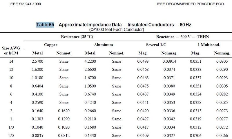
The factor f system it can be discussed. The C factor is calculated using IEEE 241/1990 pg.320 Table 65 Approximate Impedance Data Insulated Conductors 60 Hz.
Let's take 5 cables from the table:
1/0,2/0,4/0,500 mcm and 1000 mcm and let's compare with NEC 2017 Table 9, and Okonite catalogue.
First, the conductor resistance is less than "correct" calculated since factors as temperature, skin effect and proximity effect are neglected. The reactance is also less than other sources [NEC, Manufacturer]. However, recalculated the examples from page 7 using "correct" parameters from NEC 2017 Table 9 I got these results:
System A point F1 “correct” Isc1=49611A ,page 7=49803
System A point F2 “correct” Isc2= 33531A ,page 7= 35445
System B point F1 “correct” Isc1= 33088A ,page 7= 33215
System B point F2 “correct” Isc2= 30715A ,page 7= 30059
System B point F3 “correct” Isc3= 30299A ,page 7= 29731
The difference between “correct” and the way using C constant it is only 6% maximum.
 

mbrooke

Batteries Included
Location
United States
Occupation
Technician
If we are speaking about Point-To-Point Method Of Short-Circuit Calculation Cooper-Bussmann pg.7 then up to point 3 [including Notes 1 to 6] I agree with.
I don't like to use the transformer data table. Usually the impedance is less than known.
The factor f system it can be discussed. The C factor is calculated using IEEE 241/1990 pg.320 Table 65 Approximate Impedance Data Insulated Conductors 60 Hz.
Let's take 5 cables from the table:
1/0,2/0,4/0,500 mcm and 1000 mcm and let's compare with NEC 2017 Table 9, and Okonite catalogue.
First, the conductor resistance is less than "correct" calculated since factors as temperature, skin effect and proximity effect are neglected. The reactance is also less than other sources [NEC, Manufacturer]. However, recalculated the examples from page 7 using "correct" parameters from NEC 2017 Table 9 I got these results:
System A point F1 “correct” Isc1=49611A ,page 7=49803
System A point F2 “correct” Isc2= 33531A ,page 7= 35445
System B point F1 “correct” Isc1= 33088A ,page 7= 33215
System B point F2 “correct” Isc2= 30715A ,page 7= 30059
System B point F3 “correct” Isc3= 30299A ,page 7= 29731
The difference between “correct” and the way using C constant it is only 6% maximum.

6% is good enough for me.


However- what to make of this:


Note 5:The calculated short-circuit currents above represent the bolted faultvalues that approximate worst case conditions. Approximations of Bolted faultvalues as percentage of 3-Phase (L-L-L) bolted fault values are shown below.

Phase-Phase (L-L):87%

Phase-Ground (L-G) 25-125% (Use 100% near transformer, 50% otherwise)

Phase-Neutral (L-N) 25-125% (Use 100% near transformer, 50% otherwise


:?


25-125% is a big gap, at what length does 100% become 50%? And where do I use 125%? Only at the terminals?
 
Status
Not open for further replies.
Top