3 phase Delta High Leg Single Phase Load

Status
Not open for further replies.

LarryFine

Master Electrician Electric Contractor Richmond VA
Location
Henrico County, VA
Occupation
Electrical Contractor
Now in the field we see 190 volts or 208 volts on a high leg its different then calculations in a book depends on your power company or location.
Actually, the high-leg voltage was officially changed from 190v to 208v when the nominal system voltage was changed from 110/220 to 120/240. ;)
 

LarryFine

Master Electrician Electric Contractor Richmond VA
Location
Henrico County, VA
Occupation
Electrical Contractor
That being said, doesn't one winding a Scott-T transformer connect across the hi-leg to neutral???
Yes, but with a big difference that I see: using 208v from a high-leg Delta causes half of that current to travel through each half of the center-tapped winding, but in opposite directions, a way that no other connection causes.

My question is whether those opposing currents will cause heating in the core in excess of what that amount of current would normally create. Anyone have an idea?

On second thought, maybe the T connection has the same issue.
 

Smart $

Esteemed Member
Location
Ohio
Yes, but with a big difference that I see: using 208v from a high-leg Delta causes half of that current to travel through each half of the center-tapped winding, but in opposite directions, a way that no other connection causes.

My question is whether those opposing currents will cause heating in the core in excess of what that amount of current would normally create. Anyone have an idea?

On second thought, maybe the T connection has the same issue.
If I understand your thinking correctly, it doesn't cause current to flow in opposite directions at the same time. Current on the split-phase winding still flows in the same direction as the voltage from line to line with the exception of twice per cycle. That's when peak current flow in each direction occurs while line to line voltage is zero. The rest of the time, it flows either left or right aligned with the voltage. A power factor of 0 is a hard concept to wrap one's head around ;)

A Scott-T connection has the same characteristic, but the extra heating is not excessive (if I understand it correctly).
 
Last edited:

mivey

Senior Member
My question is whether those opposing currents will cause heating in the core in excess of what that amount of current would normally create. Anyone have an idea?
Funny you should ask as I just finished a calc. I used a simple transformer model with just a series impedance, a bank of three 7.2kV/240V 150 kVA transformers (1.4%R, 4.3%Z), and a resistive load of 0.275 ohms (picked for <3% unbalance).

With a quick hand calc I get:

High leg to neutral: 204.66<87.597? volts
Load: 744.23<87.597? amps, 152.3 kW
Other phases to neutral: 117.15<0.548? and 122.87<179.477? volts
Line-Line voltages: 240.00<0.000?, 242.14<237.124?, 230.52<118.094?
Voltage unbalance: 2.96%
Winding current: 372.11<87.597?
Winding Loss: 2.2 kW (1.45%)
 
Last edited:

norcal

Senior Member
One thing not mentioned about using the high leg for a 208V load is it may violate a PoCo's tariff rules to use it in that manner. (This may be a "urban legend" as have only read about that 2nd hand).
 

ohmhead

Senior Member
Location
ORLANDO FLA
Yes, but with a big difference that I see: using 208v from a high-leg Delta causes half of that current to travel through each half of the center-tapped winding, but in opposite directions, a way that no other connection causes.


Thats normal with a center tapped single phase transformer heres a question help me out here .


Well Larry that said if a transformer is center tapped on C winding you get 120 volts from B/ A to center tap back and forth polarity wise during the cycle in rotation of B to A phases this by example only is 3 phase delta not single phase its phase angle in time is different in three phase delta to connection B looking at polarity on coils during the cycles of a b c and you hook to the hi leg B is there not a point in the cycle to B phase thats a odd place in timing meaning a phase shift of time in the cycle of the connected load during the rotation of the power generated in that transformer ?


Makes me wonder a little if i put a oscope on this B phase to the C or A what would one see ?
 
Last edited:

mivey

Senior Member
One thing not mentioned about using the high leg for a 208V load is it may violate a PoCo's tariff rules to use it in that manner. (This may be a "urban legend" as have only read about that 2nd hand).
Sounds like a legend to me as they will just charge for what you use. Like with any load, you should tell them your loading so they can size the transformer correctly.
 

mivey

Senior Member
If I understand your thinking correctly, it doesn't cause current to flow in opposite directions at the same time. Current on the split-phase winding still flows in the same direction as the voltage from line to line with the exception of twice per cycle. That's when peak current flow in each direction occurs while line to line voltage is zero. The rest of the time, it flows either left or right aligned with the voltage. A power factor of 0 is a hard concept to wrap one's head around ;)
Maybe series windings is even harder to wrap one's head around.;) The zero power factor is across some series voltages.

Have you plotted the voltage and currents for the 1+1/2 coils?

No current is flowing on the other phases so it all flows through the neutral and high-leg and splits between the two 1+1/2 windings. These two 1+1/2 windings are connected in parallel across the load.

If you follow a complete path around the delta, your voltages must sum to zero. That means the voltage rise across the first 1+1/2 winding must be dropped across the second 1+1/2 winding.

A diagram would be much clearer than all this wording so if you feel froggy, post one.

Can you guess what that means?
 

mivey

Senior Member
Yes, but with a big difference that I see: using 208v from a high-leg Delta causes half of that current to travel through each half of the center-tapped winding, but in opposite directions, a way that no other connection causes.

Thats normal with a center tapped single phase transformer heres a question help me out here .


Well Larry that said if a transformer is center tapped on C winding you get 120 volts from B/ A to center tap back and forth polarity wise during the cycle in rotation of B to A phases this by example only is 3 phase delta not single phase its phase angle in time is different in three phase delta to connection B looking at polarity on coils during the cycles of a b c and you hook to the hi leg B is there not a point in the cycle to B phase thats a odd place in timing meaning a phase shift of time in the cycle of the connected load during the rotation of the power generated in that transformer ?


Makes me wonder a little if i put a oscope on this B phase to the C or A what would one see ?
Could you re-phrase the question? I'm having trouble following you.
 

Smart $

Esteemed Member
Location
Ohio
Maybe series windings is even harder to wrap one's head around.;) The zero power factor is across some series voltages.

Have you plotted the voltage and currents for the 1+1/2 coils?

No current is flowing on the other phases so it all flows through the neutral and high-leg and splits between the two 1+1/2 windings. These two 1+1/2 windings are connected in parallel across the load.

If you follow a complete path around the delta, your voltages must sum to zero. That means the voltage rise across the first 1+1/2 winding must be dropped across the second 1+1/2 winding.

A diagram would be much clearer than all this wording so if you feel froggy, post one.

Can you guess what that means?
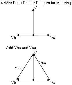
I guess my guessing isn't working that well today. If you could elaborate a bit more I might be able to oblige your request.

I posted a current vector diagram earlier in the thread... and the voltages are going to remain within nominal tolerances provided the windings are not overloaded.
 

ohmhead

Senior Member
Location
ORLANDO FLA
Could you re-phrase the question? I'm having trouble following you.


Well ok question in a different way if one took a dual trace o scope and tapped up to winding c center and tapped probe on A phase and B phase at same time would we see 180 deg between a/b to c center tap or would we see 90 deg phase shift on b only in waves at 60 hz on closed delta ?

If the load current flows back to the delta neutral is it split between right side and left side of winding meaning during the positive cycle it flows in the direction which is more or now negative in polarity on that C winding mid center and during the negative cycle it flows to the more or now posistive side ?


Correct which is which then ill ask another question .

Mivey sorry about the other post i have trouble explaining my thoughts in print but i can run conduit fine .
 
Last edited:

mivey

Senior Member
Well ok question in a different way if one took a dual trace o scope and tapped up to winding c center and tapped probe on A phase and B phase at same time would we see 180 deg between a/b to c center tap or would we see 90 deg phase shift on b only in waves at 60 hz on closed delta ?

If the load current flows back to the delta neutral is it split between right side and left side of winding meaning during the positive cycle it flows in the direction which is more or now negative in polarity on that C winding mid center and during the negative cycle it flows to the more or now posistive side ?


Correct which is which then ill ask another question .

Mivey sorry about the other post i have trouble explaining my thoughts in print but i can run conduit fine .
You will see 180 degrees between a & b to center. What we are doing is going to have very little impact on the source voltage as it is much stiffer. The current is going to split between the windings and flow according to the voltage across the load, which is a combination of the voltage on 50% of the split coil (a-n or b-n) and 100% of the voltage on the full coil (a-c or b-c).
 

mivey

Senior Member
I guess my guessing isn't working that well today. If you could elaborate a bit more I might be able to oblige your request.
I posted a current vector diagram earlier in the thread... and the voltages are going to remain within nominal tolerances provided the windings are not overloaded.
I agree the voltages will remain stable as long as the transformer is not overloaded (see #46).

What I'm saying is that current flows in opposite directions in the center-tap like Larry said. The voltage across the load is a series combination of two other voltages. With a resistive load, the current through the load is in phase with this series voltage. It may not be in phase with the 1/2 windings.

We essentially have two sources paralleled across the load. The current is evenly split across the two sources as their impedance is the same (ideally anyway). This means the current coming in at the midpoint will not be in phase with at least one of the winding halves because it is flowing toward the high-leg in both sources. It will, however, be in phase with the total series voltage across the source.

This is not as fancy as your diagram, but this is the circuit we have:

Loop voltages:
.....--------------------------
.....|............|...........|
.....|............|...........|
....Zt...........Zt...........|
.....|............|...........|
...+.|..........-.|...........|
..240<120?.....240<240?.......|
...-.|..........+.|...........|...+
.....|............|...........L
.....|............|...........O
....Zt/2.........Zt/2.........A..208<90?
.....|............|...........D
.....|............|...........|...-
...+.|..........-.|...........|
..120<0?.......120<0?.........|
...-.|..........+.|...........|
.....|............|...........|
.....-------------------------|
..............................|
...........................GND/NEU

And for those who like neutral reference voltages:
.....--------------------------
.....|............|...........|
.....|............|...........|
....Zt...........Zt...........|
.....|............|...........|
...+.|..........+.|...........|
..240<120?.....240<60?........|
...-.|..........-.|...........|...+
.....|............|...........L
.....|............|...........O
....Zt/2.........Zt/2.........A..208<90?
.....|............|...........D
.....|............|...........|...-
...+.|..........+.|...........|
..120<0?.......120<180?.......|
...-.|..........-.|...........|
.....|............|...........|
.....-------------------------|
..............................|
...........................GND/NEU
 
Last edited:

nakulak

Senior Member
that load accross the split phase could be balanced with single phase loads, just as the other single phase loads are balanced with each side of that coil. So I still don't understand, if the transformer loads are relatively balanced, what difference it makes as to whether or not some of the loads are due to 208 loads.
 

ohmhead

Senior Member
Location
ORLANDO FLA
Well looking at Smarts post it looks like its 90 degs out of phase with the other phases in the cycle of abc iam i wrong in thinking this that abc 3 phase loads are all in phase 120 * and B /CN single phase load is out of phase with the normal three phase circuits ? Meaning do to the split on center tap ?

If we look at time in place and rotation ?

I dont see it in phase with other single phase loads ?
 
Last edited:

mivey

Senior Member
Well looking at Smarts post it looks like its 90 degs out of phase with the other phases in the cycle of abc iam i wrong in thinking this that abc 3 phase loads are all in phase 120 * and B /CN single phase load is out of phase with the normal three phase circuits ? Meaning do to the split on center tap ?

If we look at time in place and rotation ?

I dont see it in phase with other single phase loads ?
I think get what what you are asking now. Before, I thought you meant just the a/b to center tap neutral.

With a neutral reference, the line-neutral voltages are 120<0?, 120<180?, 208<90? and the line-line voltages are 240<0?, 240<240?, 240<120? and will remain so except for some slight shifting. You can see this slight shift in my post #46:
Line-Neutral voltages: 117<0.548?, 123<179.5?, 205<87.6?
Line-Line voltages: 240<0.000?, 242<237.1?, 231<118.1?

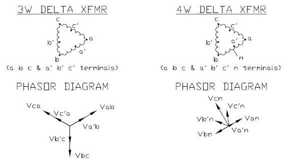
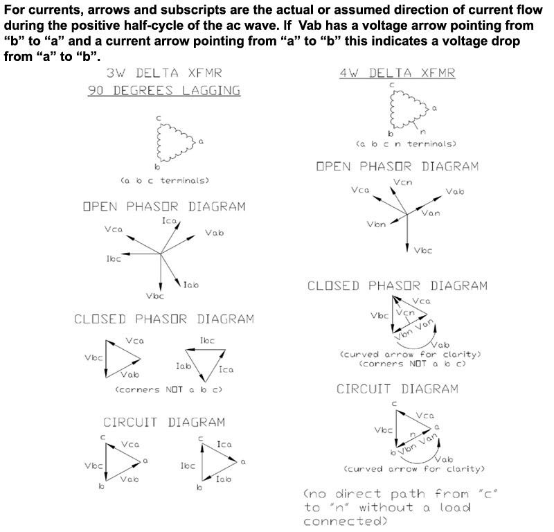
Only one line-neutral voltage will be in phase with one of the line-line voltages. Here are some phasor diagrams to illustrate the relative phase angles:

DeltaPhasors2.jpg


DeltaPhasorDiagram.jpg
 

mivey

Senior Member
Here are some phasor diagrams to illustrate the relative phase angles
Note that the a', b', c' shown in the diagrams are not the center tap position but are slightly off-center.

If I recall, the purpose of the diagram was to illustrate that while some phasor diagrams may resemble the shape of the circuit, they are not diagrams of the circuit. Sometimes people confuse the two when they have a closed phasor diagram and a delta or an open phasor diagram and a wye.

I grabbed the pics to keep from having to draw new ones. More of the phasor diagram story illustrated here:

phasorvscircuitdiagram.jpg
 
Last edited:
Status
Not open for further replies.
Top