240/120 3ph.

Status
Not open for further replies.

kwired

Electron manager
Location
NE Nebraska
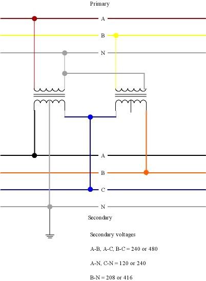
Can one of you smart guys post the picture of the open delta secondary and explain this via that picture so us not-so-smart guys can learn something?

I am confused which winding you are referring to as the 'stinger' winding.

I know and have serviced this type of system, but I want the low down on it as far as the capacities of each phase.

Thanks

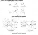
See page 9 of this Cooper publication:

http://www.cooperindustries.com/con...urces/library/201_1phTransformers/R201902.PDF

Note the symbollic diagram shows the higher-voltage-to-ground terminal as "a", which it can be on the POCO side of the service point. On the load side of the service point, the NEC requires it be connected as B [408.3(E)]

Just because your user name is Smart doesn't mean he was directly asking you:D

How about this.

Opendelta.jpg
 

Open Neutral

Senior Member
Location
Inside the Beltway
Occupation
Engineer
Just because your user name is Smart doesn't mean he was directly asking you

I know it wasn't me!
Abbot: NOW you've got it..
Costello: I don't know what I'm talking about!!!!


Given we'd like to minimize lamps blinking, and because of our P1/P2/P3 issue; I'd like to discuss my 240 loads.

Is the consensus that I put no single phase loads on A-B; or A-B & A-C? I was thinking we'd put the bigger 240V loads on A-C.

Converting from the nice color one to the official gray:
Code:
X1 - A
X0 - N
X2 - C
X3 - B  aka "the stinger tap"

Here's the official drawing:
 

Attachments

  • opendelta.jpg
    opendelta.jpg
    10.7 KB · Views: 0

jim dungar

Moderator
Staff member
Location
Wisconsin
Occupation
PE (Retired) - Power Systems
Is the consensus that I put no single phase loads on A-B; or A-B & A-C? I was thinking we'd put the bigger 240V loads on A-C.

You may put your 240V loads any where you want. Just discuss your balancing with the utility.

However any 240V loads connected to the 'stinger' leg (B phase per the NEC) will require you to the more expensive straight 240V breakers (i.e Square D type QO240H) rather than the common 120/240 slash rated ones (i.e. QO240).
 

Smart $

Esteemed Member
Location
Ohio
B is the stinger terminal. But is the "stinger winding" A-B here? I assume so.
Typically the stinger transformer secondary is considered A-B... but it can be B-C.

And do you mean "greater than B-C" or greater than A-C? Clearly A-C has the most capacity; and I assume B-C is the least, because of the [in effect] bucking windings.
Well, its hard to nail this down in the context which you phrase your question.

Consider a scenario where both lighter and stinger transformers are 24kVA. At 240V, that's 100A through each. You could connect a 100A 1? load across each secondary for a total of 48kVA. However, when you connect a balanced 100A 3? load, which is 41.6kVA of load, the 100A passing through both secondary windings max out their capacity at 48kVA. Taking it to the extreme, if you connected a 100A 1? load B-C, you'd max out the transformer bank's capacity of 48kVA with just a single 24kVA load.

Should we totally avoid any B-C loads?
Why? At best, you'd gain only 15% of the transformers' capacity, while the POCO already knows the transformers must be sized at least 15% greater than required for the connected load.
 

Smart $

Esteemed Member
Location
Ohio
...

Given we'd like to minimize lamps blinking, and because of our P1/P2/P3 issue; I'd like to discuss my 240 loads.

Is the consensus that I put no single phase loads on A-B; or A-B & A-C? I was thinking we'd put the bigger 240V loads on A-C.

...
At the design stage, it is really up to you what you put where. Ask the POCO engineer what size transformers are available. They typically use stock sizes. Then as you design, keep in mind that the transformer sizes must be determined using the current at the open-ended terminals times the winding voltage. I'm saying it this way because the transformers may be of different capacity. In the end, POCO determines transformer sizes... but knowing how they are sized helps you design loading on the system. Do you want a balanced 3? loading or do you want heavy A-N-C with light B loading? How does the design loading affect your interactive PV system? The stinger capacity should exceed your max PV B-leg out to the grid...
 

curt swartz

Electrical Contractor - San Jose, CA
Location
San Jose, CA
Occupation
Electrical Contractor
I would not use the stinger for any single phase loads. Just use it for the 3 phase loads. That is really how the open delta system is intended to be used. As Jim said you will need to use straight 240 Volt breakers which are expensive and usually special order. If you do use the stinger for any single phase loads you need to make sure they are straight 240 volt loads and not 120/240 volt. You don't want to feed an appliance that has 120 volt loads with 208 volts or bad things happen.

Another thing you need to be aware of is in your metering equipment the stinger will be in the C position. You will need to roll it to the B position in any equipment you install after the meter.
 

Open Neutral

Senior Member
Location
Inside the Beltway
Occupation
Engineer
First, OK re: un-slash breakers. Somehow I doubt their price difference will be relevant vs. the $$$$ for the service.

My goal on splitting up the 240 loads is among other things, to provide for priorities, and more relevant here: minimize light blinking. My thinking was X1-X3 loads would have the least effect on the "lighter" voltages. Other choices would have more effect. True or false?

I assume we'll get a 25/10KVA transformer, their #261547 as I said before. A HV contractor I spoke to said one {of many} PG&E issues he deals with is they refuse to use standard size transformers that other utilities do routinely. (We were discussing 208wye transformers at the time..)

On the PV issue; that's up in the air at present; but my thinking today is doing grid-tie solely on the lighter, not on the other phases. I'll be making a separate post on that issue.
 
Last edited:

Smart $

Esteemed Member
Location
Ohio
...

My goal on splitting up the 240 loads is among other things, to provide for priorities, and more relevant here: minimize light blinking. My thinking was X1-X3 loads would have the least effect on the "lighter" voltages. Other choices would have more effect. True or false?

...
According to the drawing image you posted, the stinger winding is X2-X3. 1? loads connected X2-X3 would have the least affect on X1-X2 loads. If you do connect any 1? loads to X3, try to keep motor loads X2-X3.
 

Open Neutral

Senior Member
Location
Inside the Beltway
Occupation
Engineer
3-ph net metering

3-ph net metering

This is a reverse fork from two threads: CT metering & my open delta one.

So we'll have grid-tie inverter{s} selling back via the open delta xfmr bank. Given N dollars, we could split it between all three phases, or put more KW of panels and inverters on the "lighter" phase.

I'm trying to visualize what happens when we have say 3KW of three-phase load, and single-phase grid-tie *excess* of 3KW. Is the meter really stationary?

I suspect it's more complex than just the metering. Don't retail grid-tie contracts pay less in {sell-back} than in consume?
 

Electric-Light

Senior Member
Are 240v appliances UL listed for use on a service where any part of the internal components exceeds 120v with respect to ground?
 

Open Neutral

Senior Member
Location
Inside the Beltway
Occupation
Engineer
1) On the open neutral; the grid-tie folks at PG&E tell me we can feed just the lighter winding; that allows us to use fewer inverters.

2) But I have another issue. We'd prefer to get a 3? generator for our backup, so we can run the pumps. But given the ones I have seen are 208/120 wye, I see rough waters ahead. I know 240/120/3? [ergo delta] can be had on at least one unit: a Kohler 25REZG. Can I assume the generator grounds the center tap on the lighter leg as the POCO transformer it replaces does?

And what kind of problems will the unbalanced load [heavy on the lighter, often zero on the stinger] bring us?
 
Last edited:

sameguy

Senior Member
Location
New York
Occupation
Master Elec./JW retired
You will need to follow the NEC, they will do what they like; my guess POCO will be cheaper and maintenance is on them.
 

Smart $

Esteemed Member
Location
Ohio
1) On the open neutral; the grid-tie folks at PG&E tell me we can feed just the lighter winding; that allows us to use fewer inverters.
Well, one is the minimum. Minimum of two for 3?.

Is there a question in there?


2) But I have another issue. We'd prefer to get a 3? generator for our backup, so we can run the pumps. But given the ones I have seen are 208/120 wye, I see rough waters ahead. I know 240/120/3? [ergo delta] can be had on at least one unit: a Kohler 25REZG. Can I assume the generator grounds the center tap on the lighter leg as the POCO transformer it replaces does?

And what kind of problems will the unbalanced load [heavy on the lighter, often zero on the stinger] bring us?
A gennie that matches system voltage is the more desirable... presents less problems. Many commercial-rated gennies have multiple windings that can be configured for either delta or wye system voltages.

Assuming the gennie is set up for 240/120, the grounded conductor will be the same as poco's. Should go without saying when matching system voltage.

As to the unbalanced load, don't forget that in a closed delta system, which your gennie should be, half the "lighter" phase load is output by the other windings. This is similar to closed-delta transformer supplies. If each phase winding has "z" impedance. Current obeys Ohm's Law. The direct-connected-winding path has an impedance of "(1)z", while the indirect-windings path has an impedance of "(2)z". Yes it's still unbalanced, but I'm guessing it is only half as bad as you thought :D
 

Open Neutral

Senior Member
Location
Inside the Beltway
Occupation
Engineer
Well, one is the minimum. Minimum of two for 3?.

My concern was how PG&E would feel about it; it appears they don't care if we just feed the lighter, and we shall.

A gennie that matches system voltage is the more desirable... presents less problems. Many commercial-rated gennies have multiple windings that can be configured for either delta or wye system voltages.
After hours wasted reading vague spec sheets, a vendor got back to me with a real schematic. It has at least one winding with a centertap for neutral.

If each phase winding has "z" impedance. Current obeys Ohm's Law. The direct-connected-winding path has an impedance of "(1)z", while the indirect-windings path has an impedance of "(2)z". Yes it's still unbalanced, but I'm guessing it is only half as bad as you thought
True, I'd overlooked that. I keep thinking wye.
 
Status
Not open for further replies.
Top