Metal fittings heating up

Status
Not open for further replies.

caprilister

Member
Location
Atlanta, GA
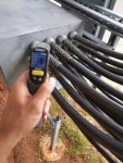
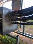
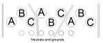
I have a solar PV system with the output of 3 AC combiners going through a metal transition box into their respective Service Disconnects.
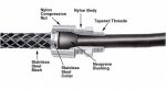
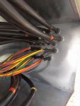
Output of the combiners goes to 3 current carrying conductors 600 kcmil CU + #3 CU neutral + #3 CU GND that penetrate the side of the transition box through a 1" cord grip. Continuous load for each combiner is 300A.

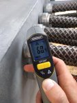
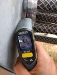
When the production of the solar array (and AC output of inverters) goes up, the cord grips heat up to 73 degrees Celsius. The temperature fluctuates quite rapidly with PV production, which leads me to believe that there is an issue with magnetic field heating up the metal fitting. Wire is USE-2 600V and there's a rubber grommet in the cord grip so only rubber is touching the wire coating. The coating of the wire not hot.
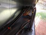
The terminations at disconnects are at constant 40 degrees.

Fitting temperature at 150A output was only 28 degrees on a cloudy day.
On a clear sky, at 250A output the temperature was 65 C.

Does anyone have any idea what would cause the heating of the fitting? And as long as the temperature stays below the wire rating (90 C) is there anything I should be worried about, especially since the grommet is rated for 105 C and the wire coating 90 so there is a good bit of buffer before those materials start to deteriorate from the heat.

Attached some photos of the arrangement and measurements.

Thanks for your help!
 

Attachments

  • IMG_20170601_173041.jpg
    IMG_20170601_173041.jpg
    148.1 KB · Views: 1
  • IMG_20170602_113222.jpg
    IMG_20170602_113222.jpg
    139.8 KB · Views: 1
  • IMG_20170602_113352.jpg
    IMG_20170602_113352.jpg
    142.8 KB · Views: 1

GoldDigger

Moderator
Staff member
Location
Placerville, CA, USA
Occupation
Retired PV System Designer
If you are talking about a single multiconductor cord containing 9 wires, then there should not be any unbalanced current in that cord to create a magnetic field that could cause heating.

If, on the other hand, you are talking about multiple conductors running through individual openings in the enclosure then it is possible that magnetic heating is playing a role.

In the first case, I would confirm that the net current in the cable is in fact zero (or close to it) using a clamp ammeter around the whole cable.

I would then check to see whether the heating is actually coming from poor terminations inside the enclosure and is just being conducted down the wires to the point where you are measuring the high temperature.
 

caprilister

Member
Location
Atlanta, GA
If, on the other hand, you are talking about multiple conductors running through individual openings in the enclosure then it is possible that magnetic heating is playing a role.

In the first case, I would confirm that the net current in the cable is in fact zero (or close to it) using a clamp ammeter around the whole cable.

I would then check to see whether the heating is actually coming from poor terminations inside the enclosure and is just being conducted down the wires to the point where you are measuring the high temperature.

GoldDigger,

thanks for the quick reply. The case is that there are 9 individual current carrying conductors in their separate openings and fittings. I checked the power factor using the power meter and it gives a consistent 1 for all the disconnects. I understand this means that the net current is zero? Conductors for each disconnect are next to each other in a triangular shape (photo). There are multiconductor wires on the bottom rows, but they don't heat up, only issue is with the 600 kcmil wires on the top rows.

I measured temperatures of the terminations at disconnects and they we around 40 deg. C. There are no splices or terminations in the transition box. Also the surface of the box on average is not hotter than ambient temperature. And if the heat was conducting from inside the enclosure, shouldn't the insulation still contain the heat from conducting to the exterior fitting? The means of heat transfer are conduction, radiation and convection, in this case conduction can be ruled out since the wire is insulated; radiation would require high temperature of the emitting surface i.e. wire coating, which is not the case. Convection is present, but is not applicable to heat transfer between the wire and fitting.

Also, there is no evident power loss between inverter output and meter reading at disconnect that would give indication to one way or another.
 

Attachments

  • GIHP power factors.jpg
    GIHP power factors.jpg
    87.6 KB · Views: 1
  • GIHP cord grip.jpg
    GIHP cord grip.jpg
    19.1 KB · Views: 1
  • qqq.jpg
    qqq.jpg
    149.4 KB · Views: 1
  • qqqa.jpg
    qqqa.jpg
    147.4 KB · Views: 1
  • qqqaaa.jpg
    qqqaaa.jpg
    146.5 KB · Views: 1

mpoulton

Senior Member
Location
Phoenix, AZ, USA
Am I understanding this correctly that those wires shown are individual conductors (not multi-conductor cables), and that they are AC (not DC from the PV array)? If so, that is definitely an induction issue. I think it's also a code issue. On what basis are you allowed to run those individual line-connected AC conductors outside a raceway?

If I'm misunderstanding and those are actually cable assemblies (how can you fit 3x 600kcmil and 2x #3 in a single 1" dia cable???), then how are they connected? Does a clamp meter around each cable show zero net AC current (as it must, if this is properly set up)?
 

caprilister

Member
Location
Atlanta, GA
The conductors in question are AC, each phase in its own 600 kcmil conductor (i.e. not a multiconductor). There are multiconductor cables in the same transition box but they don't have issues with heating. Cables are coming from an open raceway into a transition box and ultimately to service disconnect. That's why they're not in a raceway (method approved by code).
If it is indeed a question of induction, is it harmful and is there a way to reduce the heating?
 

kwired

Electron manager
Location
NE Nebraska
If you don't put all conductors of a circuit through the same ferrous enclosure, you create an electromagnet out of it. It also does introduce some inductive reactance. Other metals may have some effect but not nearly as much as ferrous metals, so if you can find reason to be able to do this you will want non ferrous materials involved.
 

GoldDigger

Moderator
Staff member
Location
Placerville, CA, USA
Occupation
Retired PV System Designer
The conductors in question are AC, each phase in its own 600 kcmil conductor (i.e. not a multiconductor). There are multiconductor cables in the same transition box but they don't have issues with heating. Cables are coming from an open raceway into a transition box and ultimately to service disconnect. That's why they're not in a raceway (method approved by code).
If it is indeed a question of induction, is it harmful and is there a way to reduce the heating?

It is questionable whether the arrangement you show is allowed by Code.
If it is, then you can cut out most of that side of the enclosure and replace it with a brass, stainless (non-magnetic) or aluminum plate, and then use non-magnetic versions of the fittings to secure the cables.

Or you can cut slots between the holes to break the magnetic circuit (but not so many that a piece can fall out!).

Or you can run all of the cables through a single opening and figure out how to properly terminate and secure them all.

BTW, a PF of 1 does not mean no net current. It means that the current and voltage waveforms are in phase with each other and undistorted.
 

caprilister

Member
Location
Atlanta, GA
So if the 3 phases go through the same penetration, they cancel each other out, which doesn't happen with a single phase.
Besides the energy that is wasted transferring to heat to the fitting, is there any potential long term harm from this?
The way I understand it, as long as the temperature rating of the wire is not exceeded, there shouldnt be any harm to the properties of the conducor
 

GoldDigger

Moderator
Staff member
Location
Placerville, CA, USA
Occupation
Retired PV System Designer
Since there is a substantial safety factor in Code ampacity tables, even if you are running right at the maximum allowed ampacity the added heating is probably not going to damage the wire.
But if you want to be a stickler you should probably recalculate the wire ampacity based on the "ambient" temperature from the magnetic heating. :angel:

Sent from my XT1585 using Tapatalk
 

caprilister

Member
Location
Atlanta, GA
Re-read Article 300.20 of the NEC... I believe you are in violation of (A).

Jraef, thanks for pointing me to the right direction! Indeed, googling with 300.20 I found a lot of information directly related to this. I didn't receive any complaints about 300.20 (A) from the inspector so I'm not that worried about that. What concerns me more is the long term effects of raised temperature.

The phases are bundled together in a triangular shape (see picture). Based on 300.20 (B) I should cut slots between the phases, does this apply between the phases from different AC combiners i.e. from 1C to 2A etc. (shown in red) too? With those slots nothing should fall off. I read somewhere that the slots shall be only a "sawblade's width".

My only concern is that does the cutting of slots actually help, if the fittings are stainless steel? I would preferably not change the fittings, so if cutting the slots would do, I'll go with that option.
 
You need to remove everything magnetic that wraps around a conductor. If the fittings are stainless, they're probably not magnetic but check with the mfg and with a magnet (check the grip wires, too). If the box is magnetic, you either need to cut the slots (only need 1/16" wide) or replace the entire plate/side. I think you'll be better off by cutting a large hole in the box and mounting a stainless or brass plate; if nothing else, it'll look a while lot better.

If you do go the slot route, fill them with putty or epoxy to keep water/critters out.
 

GoldDigger

Moderator
Staff member
Location
Placerville, CA, USA
Occupation
Retired PV System Designer
The phases are bundled together in a triangular shape (see picture). Based on 300.20 (B) I should cut slots between the phases, does this apply between the phases from different AC combiners i.e. from 1C to 2A etc. (shown in red) too? With those slots nothing should fall off. I read somewhere that the slots shall be only a "sawblade's width".

My only concern is that does the cutting of slots actually help, if the fittings are stainless steel? I would preferably not change the fittings, so if cutting the slots would do, I'll go with that option.

The slots need to be cut in such a way that each resulting single "hole" (counting the slots as part of the hole) carries only balanced current.
That means that you can treat each of the three phase plus neutral groups independently instead of also cutting holes between wires from different combiners.

For a three phase system with non-current carrying neutral you have three holes to start with and you only cut two slots (pick two sides of the triangle randomly.) If you think of the metal as a pliable sheet instead of solid you can imagine bending the center portion out to the side and you will see that there is only one real hole. If you cut three slots the center will fall out, although you do still have effectively a single hole.
 

Frank DuVal

Senior Member
Location
Fredericksburg, VA 21 Hours from Winged Horses wi
Occupation
Electrical Contractor, Electrical Engineer
Think of it this way, motors work on magnetic flux around wires acting on metal. You just built a motor that can not turn. If a motor shaft is held so it can not turn, and you apply current, things will heat up. This is what you have.

To cancel current through a metal hole, you must run all the current carrying conductors of the circuit through the same hole.
To test, use a clamp on ammeter around all the conductors going through a single hole. If there is a measurable current, then there will be a relative heating issues (and the metal will be trying to move).
 

caprilister

Member
Location
Atlanta, GA
Just to make sure, the slots should be cut something like in the attached picture?
I didn't really get the concept of folding the sheet, but this way the phases from each feeder are all together and currents don't transfer from one to another one via the steel wall.
 

Attachments

  • GIHP slots.jpg
    GIHP slots.jpg
    69.4 KB · Views: 1

kwired

Electron manager
Location
NE Nebraska
Just to make sure, the slots should be cut something like in the attached picture?
I didn't really get the concept of folding the sheet, but this way the phases from each feeder are all together and currents don't transfer from one to another one via the steel wall.

You are not putting all conductors of each circuit into a single hole, needs to look more like this:


though not a round hole, there is effectively one hole that all the conductors of the circuit pass through
only showing one three phase 5 wire circuit here, you would have do that for each individual circuit.
 

Frank DuVal

Senior Member
Location
Fredericksburg, VA 21 Hours from Winged Horses wi
Occupation
Electrical Contractor, Electrical Engineer
The sum of currents, therefore the sum of magnetic flux, through a hole has to be zero (0), or the magnetic flux will be working on the metal. This will either move it or heat it. Neither is what a wall of an enclosure should do!

All the current carrying conductors of a circuit through one hole will cancel the magnetic flux fields, therefore no heating or moving.

Canceling magnetic flux fields is the goal. Cutting slots from hole to hole helps do this. Cutting slots near holes does not.

Think Wooly Willy magnetic game (Google it if under 50 years old).:D
 

texie

Senior Member
Location
Fort Collins, Colorado
Occupation
Electrician, Contractor, Inspector
Just to make sure, the slots should be cut something like in the attached picture?
I didn't really get the concept of folding the sheet, but this way the phases from each feeder are all together and currents don't transfer from one to another one via the steel wall.

I would be inclined to not fool around with slotting due to other issues it causes such as structural integrity, etc. I would suggest cutting out the whole area and bolting in an aluminum plate.
 
Status
Not open for further replies.
Top