joe.usip
Member
- Location
- Los Angeles, CA
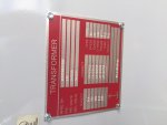
I am working on a 150 kw project where a wye to wye 480V primary 208V secondary transformer is needed. Today I received the unit, a 150 KVA autotransformer, only to find this on the name plate:


Did they sell me a step-up transformer? I know most of the time H refers to the higher voltage, on the name plate it is referring to H as the 208 side. It is an older refurbished model and I know sometimes manufacturers would use H to refer to the primary. Can I still use this in my application? Job details:
5 Solectria inverters ((3) 28TLs (2) 23Tls) 480Y output
to
200 amp load center
to
fused 200 amp disconnect
to
XFMR, 2 parallel output runs
to
fused 600 amp disco, 2 parallel runs
to
line side tap at 1600 amp 208Y switchgear