Hey guys and gals thanks for the help. Looking for the right answer in how the grounding should be accomplished to make the AHJ and the POCO happy. So here are the details...
2011 NEC
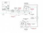
200 amp main panel feeding a 125 amp SUB in detached garage (150 feet away) via a 100 amp breaker
Sub breaker de-rated to 100 amps.
4 wire feed all CU 3 #3 and 1#8 GND.
Two ground rods driven out by the garage.
Panels, Inverter, production meter and safety disconnect are all located in or on the detached structure.
My AHJ has signed off but the POCO want the GEC to go from the inverter to the house. AHJ was ok with it going to the ground rods out at the detached structure.
2011 NEC
200 amp main panel feeding a 125 amp SUB in detached garage (150 feet away) via a 100 amp breaker
Sub breaker de-rated to 100 amps.
4 wire feed all CU 3 #3 and 1#8 GND.
Two ground rods driven out by the garage.
Panels, Inverter, production meter and safety disconnect are all located in or on the detached structure.
My AHJ has signed off but the POCO want the GEC to go from the inverter to the house. AHJ was ok with it going to the ground rods out at the detached structure.
")