320' from array to house AC or DC

Status
Not open for further replies.

ecohouse

Member
Location
Columbus, Ohio
I'm trying to design a system that includes an array that is approximately 320' from the customer's house.
I was originally thinking about having the inverter at the array and running AC back to the house, but the customer would like the inverter to be at his house, meaning DC from array to house now.

The DC will be at a higher voltage ~350V which will help with voltage drop consideration, I think....

This is where we run into a debate around the office and with other installers. What is best? and WHY?

Voltage drop is similar from AC to DC, correct? Possibly slightly less voltage drop is ideal when dealing with DC, <2%

Also, this is solaredge with optimizers, so before connected to inverter each optimizer puts out 1 volt, might see a larger loss with such a low voltage, but once turned on, I would think it's fine?

Thanks!
 

Carultch

Senior Member
Location
Massachusetts
I'm trying to design a system that includes an array that is approximately 320' from the customer's house.
I was originally thinking about having the inverter at the array and running AC back to the house, but the customer would like the inverter to be at his house, meaning DC from array to house now.

The DC will be at a higher voltage ~350V which will help with voltage drop consideration, I think....

This is where we run into a debate around the office and with other installers. What is best? and WHY?

Voltage drop is similar from AC to DC, correct? Possibly slightly less voltage drop is ideal when dealing with DC, <2%

Also, this is solaredge with optimizers, so before connected to inverter each optimizer puts out 1 volt, might see a larger loss with such a low voltage, but once turned on, I would think it's fine?

Thanks!

This article contains a nice table that rank-orders the typical voltages based on optimal traveling voltage.


1_SP3_2_pg14_QA_2-2_0.jpg


Article:
http://solarprofessional.com/articles/design-installation/voltage-drop-in-pv-systems
 

Carultch

Senior Member
Location
Massachusetts
Also, this is solaredge with optimizers, so before connected to inverter each optimizer puts out 1 volt, might see a larger loss with such a low voltage, but once turned on, I would think it's fine?

There is no voltage drop in an open circuit condition. There is only voltage drop across a wire, when current flows through it.

The current that flows through your multimeter in order to measure open circuit voltage is milliamps.
 
I'm trying to design a system that includes an array that is approximately 320' from the customer's house.
I was originally thinking about having the inverter at the array and running AC back to the house, but the customer would like the inverter to be at his house, meaning DC from array to house now.

The DC will be at a higher voltage ~350V which will help with voltage drop consideration, I think....

This is where we run into a debate around the office and with other installers. What is best? and WHY?

Voltage drop is similar from AC to DC, correct? Possibly slightly less voltage drop is ideal when dealing with DC, <2%

Also, this is solaredge with optimizers, so before connected to inverter each optimizer puts out 1 volt, might see a larger loss with such a low voltage, but once turned on, I would think it's fine?

Thanks!

Certainly the higher voltage the better for wire sizing, so that means running the strings back is going to be advantageous. The only disadvantage I can think of is that will kill the use of 1000V strings.
 

ggunn

PE (Electrical), NABCEP certified
Location
Austin, TX, USA
Occupation
Electrical Engineer - Photovoltaic Systems
I'm trying to design a system that includes an array that is approximately 320' from the customer's house.
I was originally thinking about having the inverter at the array and running AC back to the house, but the customer would like the inverter to be at his house, meaning DC from array to house now.

The DC will be at a higher voltage ~350V which will help with voltage drop consideration, I think....

This is where we run into a debate around the office and with other installers. What is best? and WHY?

Voltage drop is similar from AC to DC, correct? Possibly slightly less voltage drop is ideal when dealing with DC, <2%

Also, this is solaredge with optimizers, so before connected to inverter each optimizer puts out 1 volt, might see a larger loss with such a low voltage, but once turned on, I would think it's fine?

Thanks!
In general the effects of voltage drop are less for higher voltage runs. There is virtually no difference between AC and DC voltage drop for a given voltage and current (Table 8 vs. Table 9 resistances). Of course you can make the voltage drop be just about anything you want by changing the size (resistance) of the conductors, so it really comes down to a budget decision. Also, for a 320' run I would definitely consider aluminum conductors.
 

jaggedben

Senior Member
Location
Northern California
Occupation
Solar and Energy Storage Installer
One consideration with Solaredge is how the system handles the nominal system voltage. I have assumed, possibly without justification, that the optimizers will raise the voltage to what the inverter wants to see (e.g. 350V for single phase 240V). If that's correct then it means that, especially with Solaredge, it's better to run the DC the long way. In other words, I've assumed the SolarEdge system would be able to compensate internally on the DC lines in a much better way than the inverter/grid relationship handles on the AC side. But you might want to contact Solaredge and see if they agree... Admittedly, I've not designed a 320' DC run.
 

Besoeker

Senior Member
Location
UK
I'm trying to design a system that includes an array that is approximately 320' from the customer's house.
I was originally thinking about having the inverter at the array and running AC back to the house, but the customer would like the inverter to be at his house, meaning DC from array to house now.

The DC will be at a higher voltage ~350V which will help with voltage drop consideration, I think....

This is where we run into a debate around the office and with other installers. What is best? and WHY?

Voltage drop is similar from AC to DC, correct? Possibly slightly less voltage drop is ideal when dealing with DC, <2%

Also, this is solaredge with optimizers, so before connected to inverter each optimizer puts out 1 volt, might see a larger loss with such a low voltage, but once turned on, I would think it's fine?

Thanks!
Voltage drop should be lower with DC. There is no inductive voltage drop.
That's partly why it is used for long distance HVDC transmission.
 

Carultch

Senior Member
Location
Massachusetts
Voltage drop should be lower with DC. There is no inductive voltage drop.
That's partly why it is used for long distance HVDC transmission.

For most applications governed by the NEC, that isn't significant enough to matter until 1/0 and larger.

The fact that you have 350V instead of 240V available is the biggest reason why DC travelling voltage is better in this application.

For the AWG sized conductors 240Vac vs 240Vdc, and single phase 2-wire, both are equal. Single phase 3-wire AC has the disadvantage of the additional neutral conductor that doesn't carry significant current.

For 480Vac three phase vs 480Vdc, 3ph/3w has an advantage over its DC counterpart. Because the remaining two phases carry each phase's return current, so that every fiber of copper that carries outbound current, also carries inbound current. In the event a neutral is needed for imbalance, 3ph/4w is equal in material utilization as its DC counterpart, provided only resistive factors come in to play.

Example:
12 kW
300 ft

4x #6 Cu for AC. 14.4A
2x #3 Cu for DC. 25A

Both have 0.77% voltage drop at 480V, and the same total kcmil of copper.
 
Last edited:

Carultch

Senior Member
Location
Massachusetts
OK. But 480Vac would be about 650Vdc when rectified or would need to be about 650Vdc to invert to 480Vac.

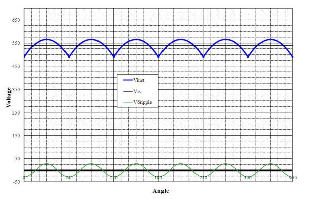
That's a good point too. The amplitude voltage of AC that we seldom mention is 41.4% higher than the nominal value. Not sure how I should interpret that, when comparing AC to DC. Should I be comparing peak voltage, or RMS voltage? Guess it depends on the exact piece of equipment that "sees" this voltage.

Would this theoretically mean that you could use 600V insulation for 848Vdc, and still keep it within its physical limit, even though the NEC limits you to 600Vdc? It has to be rated for an instantaneous voltage of 848V, in order to operate at nominal 600Vac.
 

Carultch

Senior Member
Location
Massachusetts
One consideration with Solaredge is how the system handles the nominal system voltage. I have assumed, possibly without justification, that the optimizers will raise the voltage to what the inverter wants to see (e.g. 350V for single phase 240V). If that's correct then it means that, especially with Solaredge, it's better to run the DC the long way. In other words, I've assumed the SolarEdge system would be able to compensate internally on the DC lines in a much better way than the inverter/grid relationship handles on the AC side. But you might want to contact Solaredge and see if they agree... Admittedly, I've not designed a 320' DC run.


Another thing to consider, is the consequence of voltage drop on each side. On the AC side, it turns into voltage rise at the inverter. Conservative internal relay settings, a grid voltage that is above nominal, and a high ohmic loss can result in a perfect storm that causes nuisance tripping of the internal relay. On the DC side, the MPPT trackers simply seek a lower voltage to compensate for the loss. AC side drop can cause your inverter to shut off. DC voltage drop, provided it doesn't go below the MPPT window, just means energy loss.
 

GoldDigger

Moderator
Staff member
Location
Placerville, CA, USA
Occupation
Retired PV System Designer
Just remember that for the grid interactive inverter what it sees is voltage gain rather than voltage drop. Since the current is flowing in the opposite direction it is still a power loss.

mobile
 

jaggedben

Senior Member
Location
Northern California
Occupation
Solar and Energy Storage Installer
Another thing to consider, is the consequence of voltage drop on each side. On the AC side, it turns into voltage rise at the inverter. Conservative internal relay settings, a grid voltage that is above nominal, and a high ohmic loss can result in a perfect storm that causes nuisance tripping of the internal relay. On the DC side, the MPPT trackers simply seek a lower voltage to compensate for the loss. AC side drop can cause your inverter to shut off. DC voltage drop, provided it doesn't go below the MPPT window, just means energy loss.

Well, that's all exactly right. My point, though, was about the optimizers, which (I believe) can simply raise the voltage (and lower the current) from the array to match what is best for the inverter. Thus with SolarEdge there is no worry, that I know of, about dropping out of an MPPT window. How Solaredge handles DC voltage drop is the interesting question which I don't fully know the answer to, but I would assume it has advantages over strings without optimizers.
 

Besoeker

Senior Member
Location
UK
That's a good point too. The amplitude voltage of AC that we seldom mention is 41.4% higher than the nominal value. Not sure how I should interpret that, when comparing AC to DC. Should I be comparing peak voltage, or RMS voltage? Guess it depends on the exact piece of equipment that "sees" this voltage.
The factor for conversion from 3-phase AC to DC is 1.35 assuming full wave rectification which most are.
DC inversion to AC is the reciprocal.

Would this theoretically mean that you could use 600V insulation for 848Vdc, and still keep it within its physical limit, even though the NEC limits you to 600Vdc? It has to be rated for an instantaneous voltage of 848V, in order to operate at nominal 600Vac.
I'm sorry. I'm not in NEC land so I'm not qualified to answer that.
 

Carultch

Senior Member
Location
Massachusetts
Well, that's all exactly right. My point, though, was about the optimizers, which (I believe) can simply raise the voltage (and lower the current) from the array to match what is best for the inverter. Thus with SolarEdge there is no worry, that I know of, about dropping out of an MPPT window. How Solaredge handles DC voltage drop is the interesting question which I don't fully know the answer to, but I would assume it has advantages over strings without optimizers.

Solaredge fixes the operating voltage at the inverter, and has a feedback loop to specify the output voltage among each optimizer, such that the string voltage adds up to nominal operating voltage plus the ohmic drop. It solves an algebra problem to make all series optimizers have the same current, and all voltages to be proportional to individual power, while adding up to the requisite total voltage.
 

Carultch

Senior Member
Location
Massachusetts
The factor for conversion from 3-phase AC to DC is 1.35 assuming full wave rectification which most are.
DC inversion to AC is the reciprocal.
I would guess that it is lower than 1.414, because of losses in the diodes and filtering. 1.414 or sqrt(2) is the factor for how peak AC voltage relates to RMS AC voltage. And RMS AC voltage is the equivalent DC voltage that would supply the same steady state average power to a resistive load.


I'm sorry. I'm not in NEC land so I'm not qualified to answer that.

What I'm saying, is asking the question of whether there are any cases where the peak AC voltage, instead of the RMS voltage is relevant to equipment selection. Such that you could still safely use 600VAC equipment for a 848 Vdc application. Maybe it carries a special rating for 600VAC / 850Vdc. I know the NEC has a default answer of "no" for most cases, even though 600V insulation really has to be rated for an instantaneous peak of 848V.

Looks like inductors are one example:
http://www.mouser.com/ds/2/355/RD series -794835.pdf
 
Last edited:

SolarPro

Senior Member
Location
Austin, TX
I'm trying to design a system that includes an array that is approximately 320' from the customer's house.
I was originally thinking about having the inverter at the array and running AC back to the house, but the customer would like the inverter to be at his house, meaning DC from array to house now.

The DC will be at a higher voltage ~350V which will help with voltage drop consideration, I think....

This is where we run into a debate around the office and with other installers. What is best? and WHY?

Voltage drop is similar from AC to DC, correct? Possibly slightly less voltage drop is ideal when dealing with DC, <2%

Also, this is solaredge with optimizers, so before connected to inverter each optimizer puts out 1 volt, might see a larger loss with such a low voltage, but once turned on, I would think it's fine?

Thanks!

Unless there is a compelling reason to do otherwise, you want to run the dc circuit over long distances. The dc operating voltages are higher on the dc side of the system, which will reduce wire losses. Also, as mentioned previously, the voltage rise in a long ac run could lead to nuisance tripping, especially if the grid voltage is running high for some reason. That means you're more likely to have a performance problem with a long ac run. Unless you are designing for the lower end of the inverter MPPT window, the dc side of the system is more tolerant of voltage drop.
 
Status
Not open for further replies.
Top