Since battery charging really depends on the integral of the current (the net charge moved) rather than the heating power, the straight average is the more useful measure instead of RMS.
mobile
Ok fair enough. So what is the standard way to quantify dc with ripple and other aberrations?
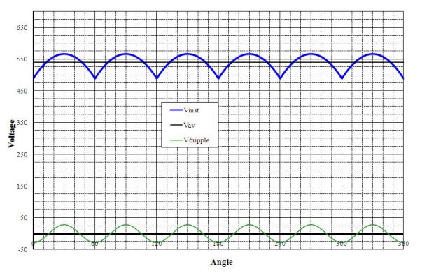
I am familiar with the 1.35 figure when rectifying three phase AC. I used it for my wind turbine where I needed a 3 phase step down transformer and then rectifier to charge batteries. But the result is obviously not true DC, so what do we call this value? For some reason I recall it was standard to refer to non pure DC voltages using the average value, not the RMS value (maybe I am making that up?).
There are more than one standard ways, but the relevance depends on what you're doing.
You can actually have RMS and Hz with DC too. It can get complex just like AC.
RMS amps and volts are values that makes resistance behave "as if it was steady DC"
The cheap efficient way to control power in DC is PWM.
Say you have a 120v DC battery plant and you have a heating device with 12kW element. (120v 100A)
You might run it full power until you get close to temperature. If the power needed to hold the temperature is 1.2kW and you're running 1 Hz PWM, you would power on for 1/10 secs and off for 9/10 secs. It's 1 Hz because this set of cycle repeats every second. 100A x 0.1S = 10As. 0A x 0.9S = 0As. This is called 10% duty cycle.
So the "average" amperage for accumulated charge flow is 10A.
The averaged heating effect of the heater is the same as running a 1.2kW heater continuously.
Recall that joule loss is amps squared times ohms. That means if you ten times the amps, the heating goes up 100 times.
RMS amps is what you have to use for cable amperage.
The cable has a voltage drop of 2v at 100A or full power. Loss at 2*100 = 200W
If you were using a real 1.2kW element, you only draw 10A at 120v. The same conductor would only drop 0.2v. So your loss is 0.2v x 10A or 2W.
what about in the case of getting 1.2kw average by running 12kW element at 10% duty cycle? Your wires lose 20w. (31.6Arms^2 * 0.632vRMS^2)
Vavg = 12v Vrms = 37.8v, Vpk = 120v (matters for battery charging)
Aavg = 10A Arms = 31.6A, Apk = 100A(peak amps matter for semiconductor devices)
The heating elements produce heat as if it was provided with steady DC of 37.8V.
The cabling produces same heat as if it was carrying 31.6A.
However, you're pulsing it at 120v DC, so you use 120v pk for shock hazard/insulation consideration.
The drawn cumulative Ah is the same but battery capacity is affected by higher RMS current.
Utility power is 120v sinewave with 170v peak. A 120v battery string connected will accept charge from 120v outlet with a simple diode and a light bulb in series even though both the RMS and average voltage would suggest below 120v. This is due to battery selectively accepting current only during the portion of the cycle that goes above charging voltage.
You could not commence charging on the same battery string with a pure 120v source without boosting voltage.