synchro
Senior Member
- Location
- Chicago, IL
- Occupation
- EE
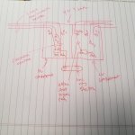
If I'm understanding Option A correctly, the return path for a 600V phase to EGC fault would be through the EGC to 15KV switchboard, then through the concentric of MV cable to X0. If that's true, will the concentric and even the 15KV switchboard adequately handle the fault current available from the 600V secondary? I'm thinking probably no, but I don't know the details of the installation you're proposing.
Also if the secondary fault current is enough to completely open the concentric conductor path over to X0, then H0/X0 will be left floating. In this case unless all three MV fuses have blown there could be high voltages on X0.
Also if the secondary fault current is enough to completely open the concentric conductor path over to X0, then H0/X0 will be left floating. In this case unless all three MV fuses have blown there could be high voltages on X0.
Last edited: